
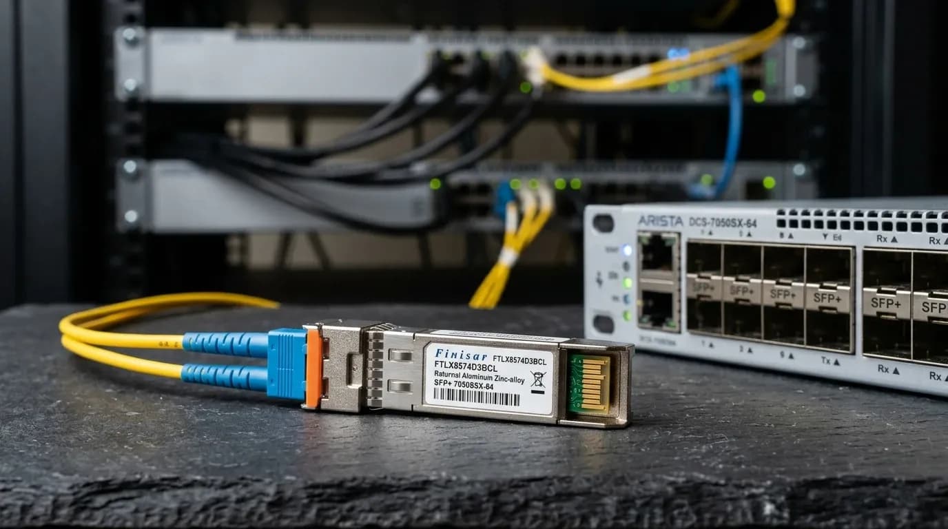
An SFP link can stay up while its optical margin disappears. That is why SFF-8472 DOM/DDM telemetry matters. It reports temperature, supply voltage, laser bias, Tx power and Rx power, but none of those readings means much in isolation. Compare the two ends of the link, the exact module datasheet and a known-good baseline before you decide that an optic has failed.
A healthy-looking dBm number is not a pass certificate. DOM supports triage; it does not replace a link-budget review, clean endfaces or calibrated measurement.
What SFF-8472 reports
A DOM-capable SFP-family module exposes five live measurements plus alarm and warning flags. The host normally reads identification and capability information from A0h and diagnostics from A2h over the module's two-wire interface. Voltage is encoded in 100 µV increments, bias in 2 µA increments and optical power in 0.1 µW increments. These are encoding scales, not operating limits.
| DOM value | Unit | What it measures | Compare it with | It does not prove |
|---|---|---|---|---|
| Temperature | °C | Module case or internal sensor | Exact module limits and prior baseline | Rack ambient temperature |
| Vcc | V | Module supply-voltage report | Datasheet limit and host evidence | The root cause of a link fault |
| Laser bias | mA | Laser drive current | Prior bias, Tx power and temperature | Remaining laser life by itself |
| Tx power | dBm or mW | Light launched locally | Exact Tx limits and remote Rx | Fibre-path loss alone |
| Rx power | dBm or mW | Light received locally | Sensitivity, overload limit and remote Tx | Which component caused the loss |
Key takeaway: Save the part number, serial number, flags and readings from both endpoints with every capture.
Tx and Rx power: read the pair
Start with the path, not the local port. Compare remote Tx with local Rx, then repeat the comparison in the other direction. If the far end transmits normally and your local Rx is low, light is being lost or received poorly somewhere between those two points. That still leaves several candidates: a dirty connector, a tight bend, wrong fibre, polarity, a weak receiver or a bad patch lead.
One milliwatt equals 0 dBm. A 3 dB change roughly doubles or halves optical power. Use the module's specified Tx, sensitivity and overload figures for decisions.
| Local observation | Remote observation | Likely direction of investigation | Validate before action |
|---|---|---|---|
| Normal Tx, low Rx | Normal remote Tx | Path loss, contamination, bend, polarity or local receiver | Clean and reseat; inspect the path; compare exact limits |
| Low Tx, low remote Rx | Low local Tx | Local transmitter, module or host-side condition | Check flags and datasheet; use a controlled swap |
| Tx alarm | Remote Rx does not track | Transmitter or telemetry issue | Confirm module thresholds and measure externally if needed |
| High Rx | Strong remote Tx | Receiver-overload risk | Check exact overload limit and attenuation design |
The link budget remains the control: $P_{budget}=P_{Tx_min}-S_{Rx_sens}$. Compare it with documented path loss and retain the project's required margin. In Dubai Internet City data centres, marginal links can look stable during commissioning then fail after a connector disturbance or thermal change.
Bias, temperature and voltage: trend the module
Laser bias, temperature and Vcc earn their place in a time series. A rising bias deserves attention when Tx power falls, temperature climbs or a flag appears. On its own, it does not predict remaining laser life. Replacing optics simply because their bias currents differ is expensive guesswork.
Treat the temperature value as a module sensor reading, not the room temperature. First compare it with the exact operating range. Then inspect airflow, nearby high-power optics and the port position. Do the same with Vcc: correlate an unusual value with host alarms and another known-good module before blaming the chassis supply.
Cisco's ASR 901 material is a useful example of how a host presents DOM thresholds and flags, but its commands and displays are platform-specific. The same caution applies when selecting compatible optics; see SFP+ transceiver compatibility on Cisco, Juniper and Arista.
Flags, calibration and measurement limits
Alarm and warning flags compare a reading to thresholds stored in that module. They do not make the same dBm, mA, Vcc or temperature value acceptable for another optic. Calibration rules also vary by module. Read the actual datasheet before treating the reported precision as field accuracy.
| Stage | Record or action | Escalate when |
|---|---|---|
| Baseline | Host, port, PN/SN, fibre type and length, both-end readings and flags | There is no trusted prior capture |
| Triage | Compare remote Tx/local Rx; inspect, clean and reseat | Values or flags persist after one controlled change |
| Escalation | Validate the link budget and measure with calibrated equipment | Margin is tight, readings conflict or acceptance is disputed |
A two-end DOM/DDM troubleshooting sequence
Capture both ends before changing hardware. In Abu Dhabi industrial SCADA networks, that discipline matters: a replacement may restore service without explaining whether vibration, routing, contamination or the module created the condition.
- Record the host model, software release, port, exact optic part number and serial, fibre type and length, DOM readings, thresholds and flags at both endpoints.
- Compare remote Tx with local Rx, then check the reciprocal direction. Inspect LC endfaces, clean and reseat them, and verify duplex polarity, media type, routing and bend condition.
- Change one variable only. Use a known-clean patch lead or a documented compatible optic, then capture the before-and-after readings from both ends.
- If the margin remains tight or the evidence conflicts, return to the design budget and use calibrated test equipment.
Protect exposed ferrules and inspect them before mating. A visual fault locator can find gross continuity or bend faults, but it cannot certify optical margin. Do not use it as a power-meter replacement.
Diagnostic tools that settle the question
DOM identifies the question. Physical tools confirm the condition.
- IEC 61300-3-35 connector inspection guidance defines an inspection and cleanliness reference; do not judge an endface by eye.
- SNIA SFF-8472 management interface is the primary reference for representation and calibration context.
- Cisco ASR 901 Digital Optical Monitoring is a platform- and release-scoped DOM example, not a generic command guide.
Use an optical power meter rated for the installed wavelength and record its calibration status.
Frequently asked questions
What does SFF-8472 DDM monitor?
It commonly reports temperature, supply voltage, laser bias, Tx power and Rx power. Availability, calibration and thresholds depend on the optic and host.
How should I interpret SFP Tx and Rx power?
Compare both readings with the exact part limits, flags and budget. Then compare remote Tx with local Rx. Low Rx identifies weak arriving light; it does not identify the cause on its own.
Does rising laser bias mean an SFP is failing?
No. Investigate a rising trend when it coincides with changing Tx power, temperature, flags or symptoms. Confirm the model-specific specification before replacing the module.
Why does an SFP report low Rx power?
Low Rx may come from weak remote output, dirty connectors, excess loss, bends, wrong media, polarity or a local receiver. Capture both ends, clean and reseat, then check the path and budget.
Are DOM and DDM the same?
They are common names for digital optical or diagnostic monitoring. What the host exposes depends on the optic, platform and software release.
Takeaways for network architects
- Treat DOM as trend and triage telemetry, never as a universal dBm, mA or °C pass/fail scale.
- Capture both endpoints. Remote Tx plus local Rx reveals more than either number alone.
- Use exact part-number thresholds, flags, calibration context and a documented link budget.
- Inspect, clean and reseat before replacement. Make one controlled change and keep the evidence.
- Escalate tight-margin or disputed results to a calibrated optical power meter.
Conclusion and UAE procurement
Good SFF-8472 DOM/DDM diagnosis turns an SFP reading into an optical-link decision. Establish the exact module limits, correlate both endpoints, then verify the physical path. For 10G multimode spans, review Alpha Bridge ASFP-10G-SR. For OS2 paths, review Alpha Bridge ASFP-10G-LR and the 10GBASE-SR vs 10GBASE-LR selection guide.
For a UAE compatibility check, provide the host and OS, port, optic part numbers, fibre type and length, DOM values and flags from both ends, plus relevant logs. Confirm Dubai stock, dispatch timing and coverage for the selected SKU before ordering.