
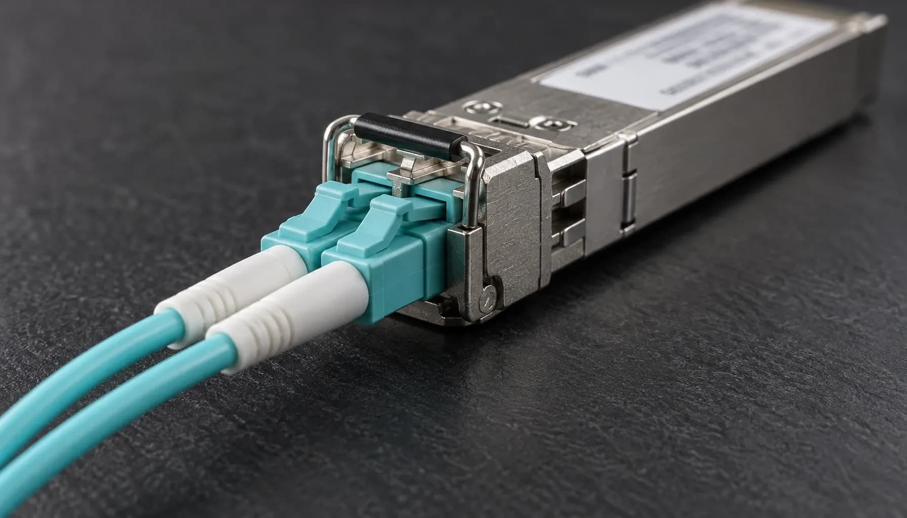
A 100G optic can pass a visual inventory check and still fail deployment because the switch SKU, software train, fiber media, lane architecture, or diagnostic headroom is wrong. In a data center high-speed migration (10g -> 25g -> 100g) installation cli configuration, treat optics as controlled hardware: identity, platform support, path budget, and live DOM must all pass before shipment or rack integration.
Acceptance Architecture: Freeze the Deployment Envelope
Use four acceptance gates. First, freeze the switch model/SKU, line card, software release, port mode, optic vendor and part number, fiber type, connector, and topology. Second, verify the module in the intended target port. Third, measure the optical path. Fourth, generate representative traffic and compare error-counter deltas. A loopback-only test cannot combine platform and path qualification.
Record serial numbers, calibration references, ambient conditions, and pass/fail evidence. Compatibility is not qualification: a QSFP28 enclosure does not establish PHY or vendor support, and breakout changes electrical semantics. Sequence these gates with the wider Data Center High-Speed Migration (10G -> 25G -> 100G): Comprehensive Engineering & Architecture Guide: The Complete UAE Engineering Guide (2026).
100G Module Comparison: Match PHY, Media and Reach
Start with the advertised PHY, then verify the vendor’s supported-part list and platform-specific exceptions.
| PHY/module | Standard/profile | Media and lane architecture | Nominal reach | DOM focus | Pre-ship metric |
|---|---|---|---|---|---|
| 100GBASE-SR4 | IEEE 802.3bm | OM3/OM4/OM5; 4×850 nm | 70 m/100 m | Per-lane or aggregate Tx/Rx, temperature, bias | Lane balance; multimode insertion loss |
| 100GBASE-DR1 | IEEE 802.3df-2024 | SMF; 1×1310 nm | 500 m | Tx/Rx, temperature, bias, voltage | End-to-end loss with project margin |
| 100GBASE-FR1 | IEEE 802.3df-2024 | SMF; 1×1310 nm | 2 km | Tx/Rx, temperature, bias, voltage | End-to-end loss with project margin |
| 100GBASE-LR1 | IEEE 802.3df-2024 | SMF; 1×1310 nm | 10 km | Tx/Rx, temperature, bias, voltage | End-to-end loss with project margin |
| 100GBASE-ER4 | IEEE 802.3bm | SMF; 4×1550 nm | 40 km | Per-wavelength or aggregate Tx/Rx, temperature, bias | Channel loss and project margin |
Reach is a media-and-implementation property, not a connector promise. Vendor parts may differ in launch power, sensitivity, and firmware behavior; legacy “LR4” is not LR1. For lane-level distinctions, use 100GBASE PHY Family Decoded: SR4, DR1, FR1, LR1 and ER4 by Lane Architecture, Media and Reach (2026).
DOM Threshold Checks: Limits Are Only One Gate
Read Limits and Live Values
DOM is module telemetry, not a link guarantee. QSFP28 management may expose module-wide or per-lane values under SFF-8431/CMIS conventions; supported fields vary. Read warning and alarm limits alongside current Tx, Rx, bias, voltage, and temperature. Before a valid far-end launch, Rx may be unavailable or zero; record “not measurable,” not “failed.”
Apply a Defensible Pass Rule
Require the exact supported part number, every measured field inside vendor limits, no active alarm, expected Tx launch level, calculated path margin, successful link, and no attributable CRC/FCS, input, or symbol-error delta. Investigate discards separately. Compare against the module datasheet and supported switch release; never reprogram thresholds to force a pass. Test temperature extremes expected in UAE deployments, not only a cool bench.
Key takeaway: DOM compliance is necessary, not sufficient; compatibility, end-to-end budget, and error-free traffic are separate acceptance gates.
Multi-Vendor Read and Verification Commands
Use read-only commands first; syntax follows the platform and release. Retain full output for the serialized record.
1# Cisco Catalyst IOS-XE2show version3show inventory4show interfaces transceiver detail5show interfaces transceiver dom thresholds6show interfaces counters errors7
8# Cisco Nexus NX-OS9show version10show interface Ethernet1/1/1 transceiver detail11show interface Ethernet1/1/1 transceiver dom thresholds12show interface Ethernet1/1/1 counters errors13
14# Arista EOS 7050X15show version16show interfaces Ethernet1/1 transceiver detail17show transceiver dom thresholds18show interfaces Ethernet1/1 counters19
20# Juniper QFX21show version22show chassis hardware23show interfaces diagnostics optics
Catalyst acceptance must include the exact C9300 SKU, uplink/stack mode, and IOS XE train; Nexus requires the exact N9K platform/line card and NX-OS release; Arista requires the 7050X SKU and EOS; QFX requires the board and Junos combination, such as QFX5120 or QFX5200. “No data” is not a pass. Normalize dBm, timestamps, and lane identifiers, then compare live readings with thresholds and pre/post traffic counters.
Reach and Platform Acceptance
At 1310 nm, budget fiber attenuation from the cable datasheet—approximately 0.35 dB/km is only a planning figure—then add connectors, splices, patch leads, and aging. At 1550 nm, use actual fiber loss because a generic value can understate it. Require project margin—commonly at least 3 dB—after all losses. Use a calibrated power meter and reference source; DOM at both ends does not replace path measurement.
For SR4, test the correct OM grade and inspect all four connectors and lane polarity. For single-mode optics, confirm SMF and matching connector polish; never mix UPC and APC. Validate reach against actual distance, not the module label. Confirm 100G versus 4×25G breakout mode and whether the selected PHY is supported. A port capable of 100G is not automatically compatible with every 100G module.
Pre-Ship Evidence and Quarantine
Create a serialized FAT/SAT record containing switch and software identity, port, optic part/serial, fiber and patch identifiers, live DOM, programmed limits, optical power, link result, traffic profile, and counter deltas. Photograph contamination, bent pins, or seal damage. Keep nonconforming modules quarantined with the failure reason; do not ship them as “spares.” Repeat identity, DOM, and link checks at rack receipt, then correlate each serial to the asset record.
Key takeaway: No module leaves the acceptance flow without a traceable part number, threshold result, link result, and operator disposition.
Frequently Asked Questions
Is a DOM reading within its limits proof that a 100G optic will pass?
No. DOM measures the module, not end-to-end quality. A module can meet its limits yet fail because the path budget is exceeded, a connector is dirty, a lane is mismatched, or the switch rejects its part number. Require supported identity, healthy DOM, a successful link, clean counters, and independent power-meter verification.
Can an SR4 module be used in a DR1 port because both use QSFP28?
No. QSFP28 describes the envelope and electrical interface, not the optical PHY. SR4 uses four 850-nm lanes over multimode; DR1, FR1, and LR1 use one 1310-nm lane over single-mode. The platform must support the exact module and PHY. A physical fit can still produce no link or an unsupported-module alarm.
What received-power margin is acceptable?
Use the module’s worst-case specifications and the actual path loss, then retain the project margin—commonly at least 3 dB. Include connector, splice, patch-lead, and aging losses, not just fiber length. Confirm launch and received power with calibrated reference equipment because DOM values from two modules are not an end-to-end measurement.
Do DOM thresholds and telemetry vary by vendor?
Yes. Limits and telemetry are vendor- and part-specific. QSFP28 management may expose module-wide or per-lane values through SFF-8431/CMIS-style pages, and supported fields vary by platform. Evaluate every warning or unsupported state against the exact part number and switch release. Never alter a threshold to make a failing module appear compliant.
Must every optic be tested in every target switch?
No. Test every optic on representative target hardware and software; use a controlled sampling plan for repeated identical batches when the SLA permits. The batch record must retain serial numbers, firmware, ports, DOM values, link results, and counter deltas. Any lot-level exception should trigger expanded testing or quarantine.
Key Takeaways
- Freeze an approved matrix linking switch SKU, release, port mode, optic part number, media, and reach.
- Require serialized identity, visual inspection, DOM readings, and supported-module status for every optic.
- Measure each path with calibrated equipment and retain project optical margin; do not infer budget from nominal reach.
- Run link and representative traffic tests, preserve counter deltas, and quarantine every exception.
- Qualify for UAE ambient temperature, dust, connector contamination, and lead-time risk before bulk shipment.
Conclusion
Pre-ship acceptance must produce one auditable answer: this exact optic is supported by this switch release, healthy at the link, and operating within the installed path’s budget. Source compatible 100G optics, supported switch hardware, and test equipment through the Strinex catalogue.