
Why OTDR specifications matter on UAE field links
A long dynamic-range figure does not make an OTDR the right instrument. In a Dubai Internet City data centre, the first connector after the front panel can matter more than a 40 km reach claim. In an Abu Dhabi industrial SCADA backhaul, reach and trace reporting may matter more than tight short-range resolution.
Buy against the route and the acceptance method. A clean trace does not prove channel loss, and a passing power reading does not locate a bad splice. Keep those jobs separate, then join the evidence before approving a handover or replacing an optic.
Technical specifications and operating principles
An OTDR sends a pulse down the fibre and measures returned backscatter and reflections. Its trace estimates the distance to connectors, splices, bends and breaks. Pulse width trades resolution for energy: a short pulse separates close events in a crowded data-hall panel, while a longer pulse reaches farther on an OS2 route. Event dead zone governs how close two reflective events can sit before the tester merges them; attenuation dead zone governs how quickly it can measure loss after a large reflection.
Use 850 nm where the installed multimode service calls for it. On OS2, commission and diagnose at 1310 nm and 1550 nm. A defect that worsens materially at 1550 nm often points to a macrobend; comparable loss at both wavelengths deserves connector and splice inspection. For live networks, apply 1625 nm only where the maintenance plan and selected module support it.
The trace also needs to agree with the interface budget:
$P_{\text{budget}} = P_{\text{Tx_min}} - S_{\text{Rx_sens}}$
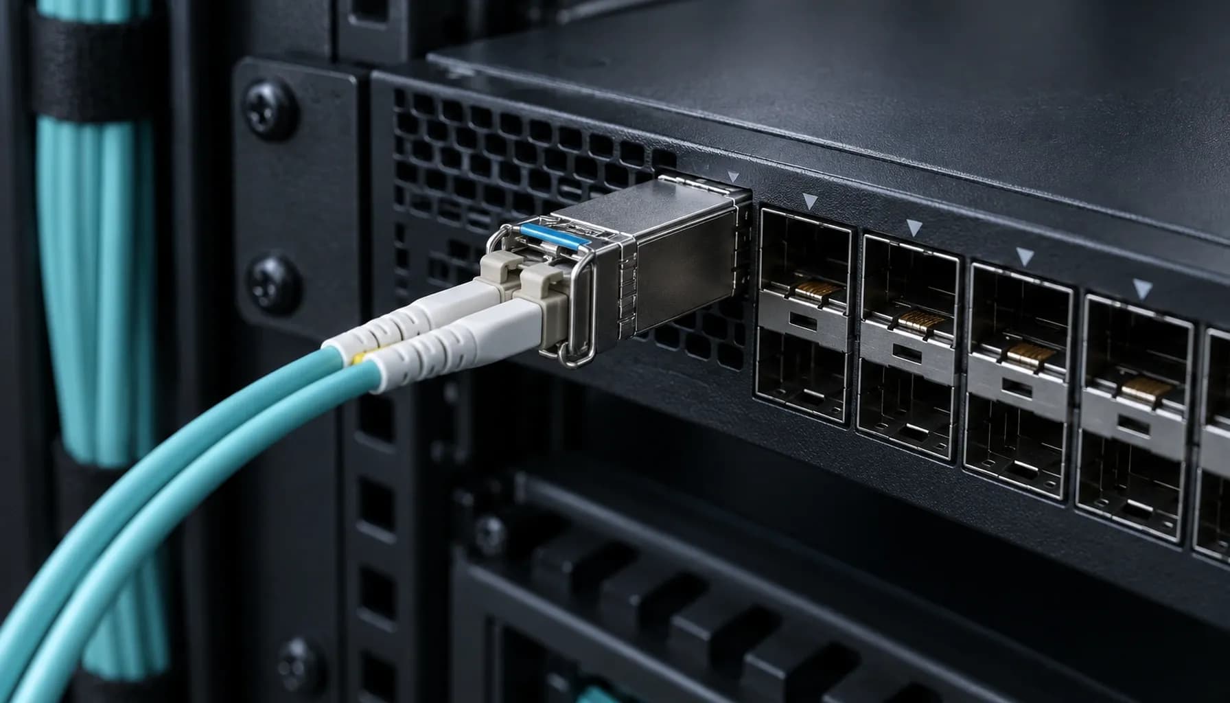
A 10G SR interface with -6.5 dBm minimum transmit power and -11.1 dBm receive sensitivity has a 4.6 dB nominal budget. Leave at least 3 dB after measured channel loss for ageing, temperature and repair work. Once the channel is proven, the Strinex 10G SR SFP+ optic provides an 850 nm, 300 m OM3/OM4 service interface with DDM. DDM is useful for trend comparison, but an SFF-8472 reading is neither an OTDR nor a calibrated power-meter result.
OTDR comparison matrix: field-fit specifications
| Decision metric | Strinex integration package | Fluke OptiFiber Pro HDR | EXFO FTB-7400E | Yokogawa / Anritsu (verify model) |
|---|---|---|---|---|
| Primary role | UAE procurement route for fibre infrastructure, launch leads, adapters, cleaning and optical remediation; not an OTDR | Field OTDR and fibre-certification workflow | Modular OTDR platform for access, enterprise and long-route testing | Dedicated test platforms; exact capability is model dependent |
| Wavelength options | Match the installed fibre and service optic | 1310/1550 nm; selected configurations add 1490 or 1625 nm | 1310/1383/1550/1625 nm options | Verify module wavelength set, including live-fibre capability |
| Published dynamic range | Not applicable | Up to 42 dB at 1310 nm, selected HDR configuration | Up to 42 dB, selected configuration | Model dependent; obtain the current data sheet |
| Dead-zone fit | Launch and receive leads support evidence at both ends | 0.7 m typical event; 4 m attenuation | 0.8 m event; 4 m attenuation | Verify event and attenuation dead zones |
| UAE commercial decision | Local stock and support depend on the item; request confirmation | Quote required; verify calibration and reseller terms | Quote required; verify calibration, service and accessories | Quote required; confirm local distributor, model and warranty |
The Strinex column is deliberately different. It describes the local support path around the test instrument, not a claim that Strinex manufactures an OTDR. That distinction prevents a bad comparison and a worse purchase order. Fluke and EXFO figures above belong to the named configurations; accessories, software options and current calibration status still need checking before procurement.
Multi-vendor interoperability and standards
The OTDR does not decide whether a Cisco, Juniper, Arista or MikroTik port will accept a replacement optic. Cisco Catalyst and Nexus, Juniper EX and QFX, Arista switching platforms and MikroTik RouterOS can all impose their own coding, speed, alarm and FEC behaviour. Collect counters and DOM readings at both ends before hardware changes.
SFF-8431 covers the SFP+ electrical interface, while SFF-8472 defines the diagnostic memory conventions used for DOM. MSA compatibility makes the data readable only when the host accepts the module; it does not bypass the host vendor's qualification policy. The evidence sequence is inspect, measure end-to-end loss, map events, compare DOM against the commissioning baseline, then validate host coding. See the UAE OTDR and fibre diagnostics guide for that workflow in more depth.
Field deployment and maintenance
Use a launch lead at the near end and a receive lead at the far end. They move the connector pairs out of the OTDR's blind zones and make the result defensible. Set a short pulse for closely spaced data-centre panels; increase it only when route loss requires more energy. Archive the native trace as well as the report, including wavelength, index of refraction, test direction, date and launch-lead identifier.
Keep fibre bends above 30 mm. Do not wind a launch lead tightly into a tester case and expect a clean 1550 nm result. Follow IEC 61300-3-35: inspect, dry-clean, inspect again, then mate. If an event looks suspect, prove it with a bidirectional OLTS or calibrated power-meter test before condemning a splice or optic.
Recommended diagnostic utilities and testing tools
- Fluke OptiFiber Pro HDR maps events and supports OTDR fault isolation on the selected wavelength configuration.
- EXFO FTB-7400E provides configurable OTDR testing for enterprise and longer OS2 routes.
- Fluke FI-3000 FiberInspector checks ferrule end faces before cleaning and mating.
Frequently asked questions
What dynamic range does an enterprise OTDR need?
Specify dynamic range from the longest, lossiest route you must test, then check that the instrument still resolves the nearest events. A high range figure brings little value to a short equipment-room link if its dead zones hide the first panel connection. Use the actual fibre count, splitters, splices and route length, not a generic enterprise label.
Which OTDR wavelengths should UAE teams test on OS2 fiber?
Use 1310 nm and 1550 nm for normal OS2 commissioning and fault isolation. Compare both traces because a macrobend usually becomes clearer at 1550 nm. Use 1625 nm only when the instrument and live-fibre maintenance procedure explicitly support it.
Why do event and attenuation dead zones matter?
They determine whether the OTDR can distinguish a close connector or splice after a large reflection. In dense rack rows, a poor dead-zone specification can conceal the event you were sent to diagnose. Launch and receive leads are the practical control for this limitation.
Can an OTDR replace optical-loss testing and transceiver DDM checks?
No. An OLTS measures end-to-end insertion loss; an OTDR locates and characterises events; DDM reports live optic telemetry. Use all three where a production link needs defensible acceptance evidence or fault isolation.
How should a UAE buyer compare OTDR prices?
Treat unverified pricing as quote required. Compare the complete field kit: wavelength module, launch leads, inspection scope, reporting software, calibration terms, repair turnaround and local support. A low instrument price can become expensive when it arrives without the accessories or service needed to close a job.
Key takeaways: UAE selection checklist
- Match test wavelength to the installed fibre: relevant multimode work at 850 nm, OS2 at 1310/1550 nm.
- Select dead-zone and pulse-width performance from the closest event, not only the route's longest span.
- Preserve at least 3 dB of optical margin after measured insertion loss.
- Inspect and clean to IEC 61300-3-35, then keep bidirectional loss results and raw traces with the handover file.
- Verify the current model, calibration, warranty and UAE quote before comparing brands.
Conclusion: local UAE procurement and support
Choose an OTDR by wavelength set, dead zones, route loss, reporting and calibration support. The brand badge comes after those constraints. For UAE teams, confirm the local stock position, dispatch commitment and regional warranty in writing; field schedules do not improve because a catalogue says a tool is available.
After the measurements isolate an interface fault, the Strinex 10G SR SFP+ optic is a live Medusa product route for short-reach restoration. Ask the Dubai team to confirm current ex-stock availability and same-day dispatch before committing a maintenance window.