Our Blog
STRINEX advances eco-friendly technologies, reducing fossil fuel reliance and supporting sustainable living. Our mission is to lead renewable energy and sustainable infrastructure through innovation and efficiency.
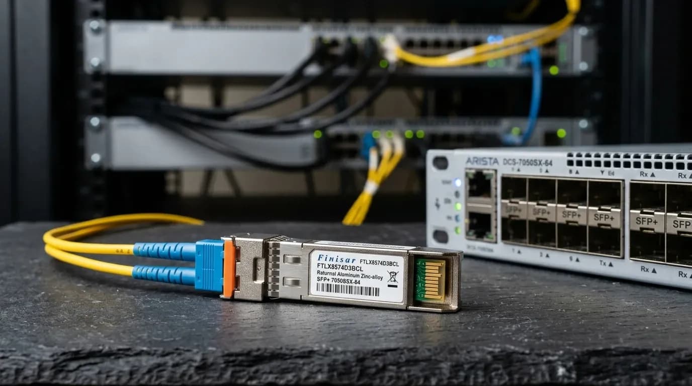
Hardened DIN-Rail Switches for Harsh Middle East Climates: The Complete UAE Engineering Guide (2026)
Introduction A DIN-rail switch in a Dubai Internet City data centre is rarely the weak point because it lacks ports. It fails because somebody treated the control-panel enclosure like an air-conditioned rack. Heat soak, conductive dust, a loose 24 VDC feed, and a poorly grounded shield can turn an ordinary access switch into an intermittent fault that steals days from commissioning. The same pattern appears in Abu Dhabi industrial SCADA networks. The Ethernet design may be sound on paper, but the installed equipment must tolerate its enclosure temperature, power quality, vibration, and electromagnetic environment. Choose a hardened switch by its documented operating envelope and protection features, then prove the complete panel design. A DIN clip alone does not make a switch industrial. Technical operating principles and specification checks Start with the electrical and environmental boundary. Confirm the switch's published temperature range at the planned load, its 24/48 VDC input range, surge and reverse-polarity protection, EMC immunity, and the enclosure's actual heat rise. If the panel reaches 68°C in summer, a 60°C commercial device has already failed its selection review. For fibre uplinks, approve the channel rather than the optic in isolation. The basic calculation is $P_{budget} = P_{Tx_min} - S_{Rx_sens}$. Available budget must cover fibre attenuation, connector and splice loss, patching, and a reserve for maintenance. DDM is useful after handover, but its thresholds belong to the fitted module; they are not a universal pass/fail scale. Use the live readings as a baseline and investigate a trend before the link begins dropping frames. For short multimode monitoring links, the Alpha Bridge ASFP-1G-SX optical transceiver is a relevant 850 nm uplink option. Match its fibre, reach, and host policy to the project. Do not select an optic because the LC connector happens to mate. Comparison matrix | Parameter | Strinex Alpha Bridge | FS.com Equivalent | Cisco OEM | Generic / Refurbished | |---|---|---|---|---| | Industrial temperature class | Confirm the exact data sheet and panel heat-rise calculation | SKU-specific; validate before release | PID-specific; validate before release | Often unclear; require evidence | | DC input and protection | Confirm voltage range, redundancy, surge, and polarity protection | SKU-specific | Platform/PID-specific | Verify label and test record | | EMC and mechanical installation | Confirm IEC test declarations, grounding point, DIN clip, and vibration rating | SKU-specific | PID-specific | Provenance and test evidence vary | | Fibre uplink policy | Match module, host approval, and measured budget | Coding and host policy matter | Native support matrix applies | Highest compatibility risk | | UAE support path | Local stock and warranty subject to availability | Confirm import lead time | Confirm authorised local stock | Confirm seller, condition, and return terms | This is deliberately not a beauty contest. Cisco OEM hardware brings a clear support path where its model fits the site. A lower-cost switch can be the better choice only when its declared limits, validation record, and replacement plan are equally clear. Interoperability and host validation Cisco, Juniper, Arista, and MikroTik can all carry the same VLANs and management traffic, but they do not share identical optic policy, alarm presentation, or Ethernet defaults. Validate the exact switch model, software release, copper or fibre port mode, VLAN tagging, STP role, LLDP behavior, and multicast settings in a small acceptance rack before the field crew installs anything. For optical diagnostics, use the SFF-8472 DOM/DDM field guide to capture Tx/Rx power, temperature, voltage, bias, flags, part number, and serial number at both ends. A link-up LED only confirms a moment in time. It does not prove a compatible EEPROM, adequate margin, or a resilient trunk. Keep one approved spare configuration per switch family. That means the same switch software baseline, exact optic, fibre type, and known-good configuration. It is cheaper than diagnosing a mixed estate during an outage. Field deployment and maintenance Mount the switch where airflow is real, not assumed. Separate heat-producing power supplies from sensitive Ethernet gear, leave service access for terminals and fibre, and bond the panel according to the product documentation. Shielded cable helps only when the bonding scheme is deliberate; a casually terminated screen can create a new noise path. Keep optical service loops above a $>30\text{ mm}$ bend radius unless the cable maker permits a tighter value. Label each end, preserve duplex polarity, and cap unused connectors. A sharply dressed cable route may look tidy while quietly consuming the last margin in the link budget. Treat connector cleaning as a procedure, not a gesture. Follow IEC 61300-3-35 practice: inspect, dry-clean, inspect again, then mate. Do not touch the ferrule or blow on it. After a repair, record two-ended DOM values and compare them with the acceptance baseline; use calibrated loss testing when the route includes splices, unexplained attenuation, or a disputed handover. Recommended diagnostic utilities and testing tools Fluke Networks FiberInspector Pro finds contamination and endface damage before a connector is mated. Fluke Networks CertiFiber Pro OLTS measures fibre loss and length against the channel requirement. EXFO MaxTester OTDR locates bends, splice events, and distance-to-fault on longer routes. Frequently asked questions What temperature rating should an industrial DIN-rail switch have? Choose against the measured enclosure temperature, not the outdoor weather report. Include heat from DC supplies, drives, solar gain, and adjacent equipment. The selected switch must remain within its published operating range at the installed load. Does an IP rating prove a switch is suitable for a control panel? No. An IP rating addresses defined ingress conditions, not DC supply tolerance, EMC immunity, vibration, or enclosure heat rise. Review all of those properties with the switch documentation and panel design. Can Cisco, Juniper, Arista, and MikroTik use the same fibre optic? Sometimes, but MSA form factor alone is not sufficient. Each host can enforce different EEPROM, software, and support policies. Validate the exact module and release in a test rack, then retain the result with the site records. Does DDM replace a fibre acceptance test? No. DDM provides operational telemetry that is excellent for baselines and troubleshooting. An OLTS or calibrated optical power meter validates physical loss against the approved channel budget. How often should fibre connectors be cleaned? Inspect before every critical mate or re-mate, then clean only when inspection requires it. Protect disconnected ends with caps and keep cleaning tools in the panel kit. Unnecessary contact is also a contamination risk. Key takeaways: UAE selection checklist Select for the measured panel environment: temperature, DC input, surge exposure, EMC, grounding, and vibration. Calculate $P_{budget} = P_{Tx_min} - S_{Rx_sens}$ and keep documented loss and maintenance reserve. Validate the exact switch, software release, optic, VLAN behavior, and monitoring before field deployment. Maintain bend radius above $>30\text{ mm}$ unless the cable specification says otherwise, and follow IEC 61300-3-35 inspection discipline. Keep a validated spare and two-ended diagnostic baseline at every critical site. Conclusion and local UAE procurement Hardened DIN-rail switching succeeds when the cabinet, power system, cable plant, and host configuration are reviewed as one operating system. Spend the engineering effort before installation: measure the enclosure, validate interoperability, document the budget, and preserve the commissioning baseline. For UAE projects, Strinex can check local Dubai stock and same-day dispatch availability for the required product configuration. Review the live Strinex networking catalogue , then provide the panel temperature, DC supply, port count, fibre type, route length, and required host platforms for a precise selection.

Categories
Popular Tags
Hardened DIN-Rail Switches for Harsh Middle East Climates: The Complete UAE Engineering Guide (2026)
Introduction A DIN-rail switch in a Dubai Internet City data centre is rarely the weak point because it lacks ports. It fails because somebody treated the control-panel enclosure like an air-conditioned rack. Heat soak, conductive dust, a loose 24 VDC feed, and a poorly grounded shield can turn an ordinary access switch into an intermittent fault that steals days from commissioning. The same pattern appears in Abu Dhabi industrial SCADA networks. The Ethernet design may be sound on paper, but the installed equipment must tolerate its enclosure temperature, power quality, vibration, and electromagnetic environment. Choose a hardened switch by its documented operating envelope and protection features, then prove the complete panel design. A DIN clip alone does not make a switch industrial. Technical operating principles and specification checks Start with the electrical and environmental boundary. Confirm the switch's published temperature range at the planned load, its 24/48 VDC input range, surge and reverse-polarity protection, EMC immunity, and the enclosure's actual heat rise. If the panel reaches 68°C in summer, a 60°C commercial device has already failed its selection review. For fibre uplinks, approve the channel rather than the optic in isolation. The basic calculation is $P_{budget} = P_{Tx_min} - S_{Rx_sens}$. Available budget must cover fibre attenuation, connector and splice loss, patching, and a reserve for maintenance. DDM is useful after handover, but its thresholds belong to the fitted module; they are not a universal pass/fail scale. Use the live readings as a baseline and investigate a trend before the link begins dropping frames. For short multimode monitoring links, the Alpha Bridge ASFP-1G-SX optical transceiver is a relevant 850 nm uplink option. Match its fibre, reach, and host policy to the project. Do not select an optic because the LC connector happens to mate. Comparison matrix | Parameter | Strinex Alpha Bridge | FS.com Equivalent | Cisco OEM | Generic / Refurbished | |---|---|---|---|---| | Industrial temperature class | Confirm the exact data sheet and panel heat-rise calculation | SKU-specific; validate before release | PID-specific; validate before release | Often unclear; require evidence | | DC input and protection | Confirm voltage range, redundancy, surge, and polarity protection | SKU-specific | Platform/PID-specific | Verify label and test record | | EMC and mechanical installation | Confirm IEC test declarations, grounding point, DIN clip, and vibration rating | SKU-specific | PID-specific | Provenance and test evidence vary | | Fibre uplink policy | Match module, host approval, and measured budget | Coding and host policy matter | Native support matrix applies | Highest compatibility risk | | UAE support path | Local stock and warranty subject to availability | Confirm import lead time | Confirm authorised local stock | Confirm seller, condition, and return terms | This is deliberately not a beauty contest. Cisco OEM hardware brings a clear support path where its model fits the site. A lower-cost switch can be the better choice only when its declared limits, validation record, and replacement plan are equally clear. Interoperability and host validation Cisco, Juniper, Arista, and MikroTik can all carry the same VLANs and management traffic, but they do not share identical optic policy, alarm presentation, or Ethernet defaults. Validate the exact switch model, software release, copper or fibre port mode, VLAN tagging, STP role, LLDP behavior, and multicast settings in a small acceptance rack before the field crew installs anything. For optical diagnostics, use the SFF-8472 DOM/DDM field guide to capture Tx/Rx power, temperature, voltage, bias, flags, part number, and serial number at both ends. A link-up LED only confirms a moment in time. It does not prove a compatible EEPROM, adequate margin, or a resilient trunk. Keep one approved spare configuration per switch family. That means the same switch software baseline, exact optic, fibre type, and known-good configuration. It is cheaper than diagnosing a mixed estate during an outage. Field deployment and maintenance Mount the switch where airflow is real, not assumed. Separate heat-producing power supplies from sensitive Ethernet gear, leave service access for terminals and fibre, and bond the panel according to the product documentation. Shielded cable helps only when the bonding scheme is deliberate; a casually terminated screen can create a new noise path. Keep optical service loops above a $>30\text{ mm}$ bend radius unless the cable maker permits a tighter value. Label each end, preserve duplex polarity, and cap unused connectors. A sharply dressed cable route may look tidy while quietly consuming the last margin in the link budget. Treat connector cleaning as a procedure, not a gesture. Follow IEC 61300-3-35 practice: inspect, dry-clean, inspect again, then mate. Do not touch the ferrule or blow on it. After a repair, record two-ended DOM values and compare them with the acceptance baseline; use calibrated loss testing when the route includes splices, unexplained attenuation, or a disputed handover. Recommended diagnostic utilities and testing tools Fluke Networks FiberInspector Pro finds contamination and endface damage before a connector is mated. Fluke Networks CertiFiber Pro OLTS measures fibre loss and length against the channel requirement. EXFO MaxTester OTDR locates bends, splice events, and distance-to-fault on longer routes. Frequently asked questions What temperature rating should an industrial DIN-rail switch have? Choose against the measured enclosure temperature, not the outdoor weather report. Include heat from DC supplies, drives, solar gain, and adjacent equipment. The selected switch must remain within its published operating range at the installed load. Does an IP rating prove a switch is suitable for a control panel? No. An IP rating addresses defined ingress conditions, not DC supply tolerance, EMC immunity, vibration, or enclosure heat rise. Review all of those properties with the switch documentation and panel design. Can Cisco, Juniper, Arista, and MikroTik use the same fibre optic? Sometimes, but MSA form factor alone is not sufficient. Each host can enforce different EEPROM, software, and support policies. Validate the exact module and release in a test rack, then retain the result with the site records. Does DDM replace a fibre acceptance test? No. DDM provides operational telemetry that is excellent for baselines and troubleshooting. An OLTS or calibrated optical power meter validates physical loss against the approved channel budget. How often should fibre connectors be cleaned? Inspect before every critical mate or re-mate, then clean only when inspection requires it. Protect disconnected ends with caps and keep cleaning tools in the panel kit. Unnecessary contact is also a contamination risk. Key takeaways: UAE selection checklist Select for the measured panel environment: temperature, DC input, surge exposure, EMC, grounding, and vibration. Calculate $P_{budget} = P_{Tx_min} - S_{Rx_sens}$ and keep documented loss and maintenance reserve. Validate the exact switch, software release, optic, VLAN behavior, and monitoring before field deployment. Maintain bend radius above $>30\text{ mm}$ unless the cable specification says otherwise, and follow IEC 61300-3-35 inspection discipline. Keep a validated spare and two-ended diagnostic baseline at every critical site. Conclusion and local UAE procurement Hardened DIN-rail switching succeeds when the cabinet, power system, cable plant, and host configuration are reviewed as one operating system. Spend the engineering effort before installation: measure the enclosure, validate interoperability, document the budget, and preserve the commissioning baseline. For UAE projects, Strinex can check local Dubai stock and same-day dispatch availability for the required product configuration. Review the live Strinex networking catalogue , then provide the panel temperature, DC supply, port count, fibre type, route length, and required host platforms for a precise selection.
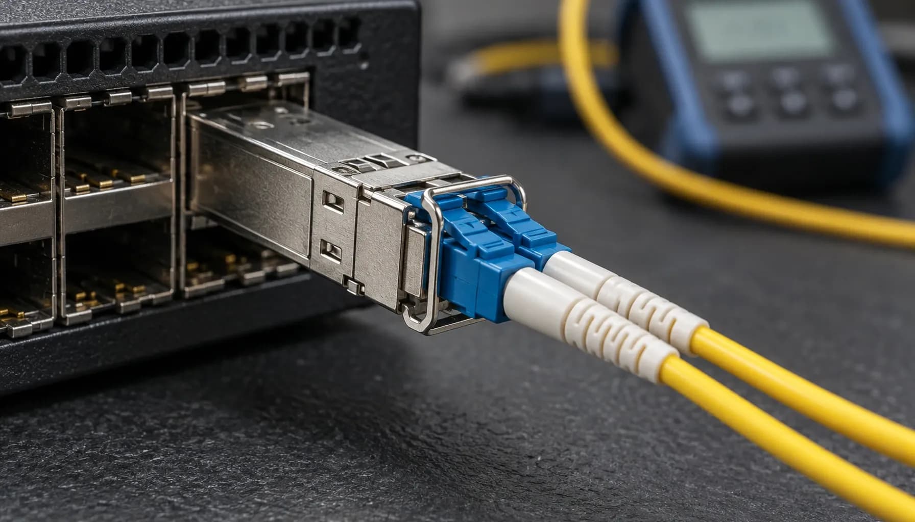
Single-Mode (OS2) vs Multi-Mode (OM3/OM4) Infrastructure: Comprehensive Engineering & Architecture Guide: The Complete UAE Engineering Guide (2026)
The correct fibre decision is made from the measured channel and its growth horizon—not from the lowest transceiver line price. This single-mode (OS2) vs multi-mode (OM3/OM4) infrastructure enterprise guide UAE sets the boundary clearly: use OM3/OM4 for short, contained 850 nm data-centre channels that already qualify; build OS2 where distance, campus reach, WDM options, or a long refresh cycle govern the architecture. For new inter-building, industrial, and large data-centre backbone routes in the UAE, OS2 is the default. Multimode remains efficient inside a defined equipment room. Optical physics, reach, and the loss budget OM3 and OM4 are 50/125 µm laser-optimised multimode fibres, normally paired with 850 nm VCSEL optics. At 10 GbE, 10GBASE-SR is commonly designed for 300 m on OM3 and 400 m on OM4. OS2 is 9/125 µm single-mode fibre, normally paired with 1310 nm LR optics; 10GBASE-LR is commonly specified to 10 km on a compliant G.652 channel. These are application limits, not a substitute for acceptance testing. The governing calculation is $P_{budget}=P_{Tx_min}-S_{Rx_sens}$. Available budget must exceed fibre attenuation, connector loss, splice loss, patching loss and a design reserve. Retain at least 3 dB of safety margin where the application budget permits. A short OS2 LR link also needs an overload check; a receiver can be too strongly illuminated even when the budget looks generous. For an in-rack or same-hall 10 GbE channel, the Alpha Bridge ASFP-10G-SR 10G SFP+ optical transceiver is a correctly matched 850 nm, LC-duplex multimode option with a stated 300 m reach and DDM. Do not install it on OS2 simply because the connector fits. DDM/DOM provides the operational evidence after commissioning. SFF-8472-capable modules expose diagnostics on the two-wire serial interface, conventionally at address 0xA2: temperature, supply voltage, laser bias, Tx power, Rx power, thresholds and flags. Trend both ends. A stable link state is not proof that remaining optical margin is healthy. **Key takeaway:** Select the fibre and optic as one optical system, then approve the route only after measured loss is below the calculated budget with reserve. Comparison matrix for high-density infrastructure | Parameter | Strinex Alpha Bridge | FS.com Equivalent | Cisco OEM | Generic / Refurbished | |---|---|---|---|---| | Data Rate / Power Rating | 10G SR; 3.3 V, low-power SFP+ class | 10G SR class; verify exact SKU | 10G SR class; exact PID governs | Varies; label is insufficient | | Wavelength / Fiber Type | 850 nm, OM3/OM4 MMF | Usually 850 nm, OM3/OM4 MMF | 850 nm SR or 1310 nm LR by PID | May be mismatched or undocumented | | Max Reach / Range | Stated 300 m for ASFP-10G-SR | SKU-specific; validate | Application/PID-specific | Must be tested, not assumed | | DDM / DOM Telemetry | DDM stated | SKU-specific | Platform/PID-specific | Often inconsistent | | Switch Compatibility | MSA basis; validate host policy | Coding and host policy matter | Native supported matrix | Highest interoperability risk | | UAE Delivery Time | Ex-stock Dubai, same-day dispatch when available | Typically 4–7 days overseas | Depends on authorised stock | Variable local availability | | Regional Warranty | Local 5-year product warranty stated | Seller-dependent | OEM support contract dependent | Often limited or unclear | Local replacement stock reduces repair time when a line-card optic fails in a change window. The Strinex 10G/25G Optical Transceivers listing is a starting point for SR-class stock, but final selection follows the host interface, fibre type, temperature class and measured channel. Multi-vendor switch compatibility and interoperability MSA electrical compliance is necessary but not sufficient. SFF-8431 defines the SFP+ electrical interface, while SFF-8472 defines diagnostic management information. The module EEPROM identifies its capabilities and vendor coding; the host reads it and may enforce a platform-specific policy. Cisco Catalyst and Nexus, Juniper EX/QFX, Arista 7050SX, and MikroTik RouterOS therefore need a lab validation with the exact software release and port mode before production rollout. Check speed negotiation, FEC where applicable, breakout configuration, supported optical power, and vendor-optic enforcement separately. An electrically accepted module can still fail because the port speed or fibre polarity is wrong. Use SFF-8472 DOM/DDM Diagnostics: Reading Tx/Rx Power, Bias & Temperature on SFP Modules (2026) : capture the exact part number, flags, and readings from both ends before declaring an optic defective. Avoid blanket “third-party optic” assumptions. Establish one approved module pair per switch family, retain the compatibility evidence, and keep an identical validated spare for each critical site. Field deployment, insertion loss, and maintenance Maintain a bend radius greater than 30 mm unless the cable assembly permits less. Keep service loops restrained, use correct LC duplex polarity, and label fibre type and endpoint. Follow the connector geometry specified for the installed system. Contamination remains the most common avoidable loss source. Apply IEC 61300-3-35 discipline: inspect, dry-clean, inspect again, then mate. Never touch an LC ferrule or clean a connector by blowing on it. After any repair, validate the route with an optical power meter against the launch power and receiver requirements; use an OLTS or OTDR where the fault domain includes the installed cable plant, splices, or unexplained events. Recommended Diagnostic Utilities & Testing Tools Use a hierarchy: inspect the endface, confirm polarity and optic identity, read DOM at both endpoints, then measure insertion loss before escalating to trace analysis. This sequence prevents a contaminated patch lead from becoming an unnecessary transceiver replacement. Fluke Networks FiberInspector Pro inspects LC endfaces so contamination is found before mating. Fluke Networks CertiFiber Pro OLTS measures loss and length against a documented fibre-channel standard. EXFO MaxTester OTDR locates events, bends, and splice anomalies on longer OS2 routes. Frequently asked questions Should a new UAE data-centre backbone use OS2? Yes, OS2 is normally the stronger default for a new backbone. It supports long reaches and future optical application choices without replacing the permanent cable plant. Use measured attenuation and expected port speeds to select the eventual transceiver class. Is OM4 always better than OM3? No, OM4 is not automatically a better installed channel. Its reach advantage matters only when the active application and route length need it. Existing qualified OM3 remains appropriate for compliant short SR links. Can an SR SFP+ module operate over OS2? No, an 850 nm SR module is designed for multimode fibre, not OS2 single-mode fibre. The LC connector compatibility is mechanical only. Use a correctly specified LR or other single-mode application at both ends. How much optical margin should the design retain? Keep at least 3 dB where the application budget allows it. That reserve absorbs connector ageing, maintenance variation, and modest channel changes. It does not remove the need to check receiver overload on short single-mode links. Does DOM replace an optical power-meter test? No, DOM is operational telemetry rather than calibrated channel certification. It is valuable for trending Tx, Rx, bias, voltage, and temperature against a baseline. Use a power meter or OLTS to validate the physical loss budget. Key takeaways: UAE selection checklist Default new backbone and inter-building routes to OS2 when future reach or WDM flexibility matters. Keep OM3/OM4 SR channels inside their qualified distance and application envelope. Calculate $P_{budget}=P_{Tx_min}-S_{Rx_sens}$ and preserve at least 3 dB of margin where feasible. Validate host policy, EEPROM recognition, port mode, polarity, and DOM on the exact switch software release. Inspect and dry-clean every LC interface, then record two-ended optical readings after acceptance. Conclusion & local UAE procurement A disciplined fibre choice avoids needless OS2 optics on a short qualified SR channel and the far costlier mistake of placing a limited multimode trunk into a future backbone. The single-mode (OS2) vs multi-mode (OM3/OM4) infrastructure enterprise guide UAE decision follows the measured media, route loss, switch constraints, operating temperature and growth plan. Strinex holds relevant UAE stock through its Dubai fulfilment operation for same-day dispatch when inventory is available, with regional warranty support. Select the exact optic only after the above checks, then request availability or a quote through the Alpha Bridge ASFP-10G-SR 10G SFP+ optical transceiver page.
SFF-8472 DOM/DDM Diagnostics: Reading Tx/Rx Power, Bias & Temperature on SFP Modules (2026)
An SFP link can stay up while its optical margin disappears. That is why SFF-8472 DOM/DDM telemetry matters. It reports temperature, supply voltage, laser bias, Tx power and Rx power, but none of those readings means much in isolation. Compare the two ends of the link, the exact module datasheet and a known-good baseline before you decide that an optic has failed. A healthy-looking dBm number is not a pass certificate. DOM supports triage; it does not replace a link-budget review, clean endfaces or calibrated measurement. What SFF-8472 reports A DOM-capable SFP-family module exposes five live measurements plus alarm and warning flags. The host normally reads identification and capability information from A0h and diagnostics from A2h over the module's two-wire interface. Voltage is encoded in 100 µV increments, bias in 2 µA increments and optical power in 0.1 µW increments. These are encoding scales, not operating limits. | DOM value | Unit | What it measures | Compare it with | It does not prove | |---|---|---|---|---| | Temperature | °C | Module case or internal sensor | Exact module limits and prior baseline | Rack ambient temperature | | Vcc | V | Module supply-voltage report | Datasheet limit and host evidence | The root cause of a link fault | | Laser bias | mA | Laser drive current | Prior bias, Tx power and temperature | Remaining laser life by itself | | Tx power | dBm or mW | Light launched locally | Exact Tx limits and remote Rx | Fibre-path loss alone | | Rx power | dBm or mW | Light received locally | Sensitivity, overload limit and remote Tx | Which component caused the loss | Key takeaway: Save the part number, serial number, flags and readings from both endpoints with every capture. Tx and Rx power: read the pair Start with the path, not the local port. Compare remote Tx with local Rx, then repeat the comparison in the other direction. If the far end transmits normally and your local Rx is low, light is being lost or received poorly somewhere between those two points. That still leaves several candidates: a dirty connector, a tight bend, wrong fibre, polarity, a weak receiver or a bad patch lead. One milliwatt equals 0 dBm. A 3 dB change roughly doubles or halves optical power. Use the module's specified Tx, sensitivity and overload figures for decisions. | Local observation | Remote observation | Likely direction of investigation | Validate before action | |---|---|---|---| | Normal Tx, low Rx | Normal remote Tx | Path loss, contamination, bend, polarity or local receiver | Clean and reseat; inspect the path; compare exact limits | | Low Tx, low remote Rx | Low local Tx | Local transmitter, module or host-side condition | Check flags and datasheet; use a controlled swap | | Tx alarm | Remote Rx does not track | Transmitter or telemetry issue | Confirm module thresholds and measure externally if needed | | High Rx | Strong remote Tx | Receiver-overload risk | Check exact overload limit and attenuation design | The link budget remains the control: $P_{budget}=P_{Tx_min}-S_{Rx_sens}$. Compare it with documented path loss and retain the project's required margin. In Dubai Internet City data centres, marginal links can look stable during commissioning then fail after a connector disturbance or thermal change. Bias, temperature and voltage: trend the module Laser bias, temperature and Vcc earn their place in a time series. A rising bias deserves attention when Tx power falls, temperature climbs or a flag appears. On its own, it does not predict remaining laser life. Replacing optics simply because their bias currents differ is expensive guesswork. Treat the temperature value as a module sensor reading, not the room temperature. First compare it with the exact operating range. Then inspect airflow, nearby high-power optics and the port position. Do the same with Vcc: correlate an unusual value with host alarms and another known-good module before blaming the chassis supply. Cisco's ASR 901 material is a useful example of how a host presents DOM thresholds and flags, but its commands and displays are platform-specific. The same caution applies when selecting compatible optics; see SFP+ transceiver compatibility on Cisco, Juniper and Arista . Flags, calibration and measurement limits Alarm and warning flags compare a reading to thresholds stored in that module. They do not make the same dBm, mA, Vcc or temperature value acceptable for another optic. Calibration rules also vary by module. Read the actual datasheet before treating the reported precision as field accuracy. | Stage | Record or action | Escalate when | |---|---|---| | Baseline | Host, port, PN/SN, fibre type and length, both-end readings and flags | There is no trusted prior capture | | Triage | Compare remote Tx/local Rx; inspect, clean and reseat | Values or flags persist after one controlled change | | Escalation | Validate the link budget and measure with calibrated equipment | Margin is tight, readings conflict or acceptance is disputed | A two-end DOM/DDM troubleshooting sequence Capture both ends before changing hardware. In Abu Dhabi industrial SCADA networks, that discipline matters: a replacement may restore service without explaining whether vibration, routing, contamination or the module created the condition. Record the host model, software release, port, exact optic part number and serial, fibre type and length, DOM readings, thresholds and flags at both endpoints. Compare remote Tx with local Rx, then check the reciprocal direction. Inspect LC endfaces, clean and reseat them, and verify duplex polarity, media type, routing and bend condition. Change one variable only. Use a known-clean patch lead or a documented compatible optic, then capture the before-and-after readings from both ends. If the margin remains tight or the evidence conflicts, return to the design budget and use calibrated test equipment. Protect exposed ferrules and inspect them before mating. A visual fault locator can find gross continuity or bend faults, but it cannot certify optical margin. Do not use it as a power-meter replacement. Diagnostic tools that settle the question DOM identifies the question. Physical tools confirm the condition. IEC 61300-3-35 connector inspection guidance defines an inspection and cleanliness reference; do not judge an endface by eye. SNIA SFF-8472 management interface is the primary reference for representation and calibration context. Cisco ASR 901 Digital Optical Monitoring is a platform- and release-scoped DOM example, not a generic command guide. Use an optical power meter rated for the installed wavelength and record its calibration status. Frequently asked questions What does SFF-8472 DDM monitor? It commonly reports temperature, supply voltage, laser bias, Tx power and Rx power. Availability, calibration and thresholds depend on the optic and host. How should I interpret SFP Tx and Rx power? Compare both readings with the exact part limits, flags and budget. Then compare remote Tx with local Rx. Low Rx identifies weak arriving light; it does not identify the cause on its own. Does rising laser bias mean an SFP is failing? No. Investigate a rising trend when it coincides with changing Tx power, temperature, flags or symptoms. Confirm the model-specific specification before replacing the module. Why does an SFP report low Rx power? Low Rx may come from weak remote output, dirty connectors, excess loss, bends, wrong media, polarity or a local receiver. Capture both ends, clean and reseat, then check the path and budget. Are DOM and DDM the same? They are common names for digital optical or diagnostic monitoring. What the host exposes depends on the optic, platform and software release. Takeaways for network architects Treat DOM as trend and triage telemetry, never as a universal dBm, mA or °C pass/fail scale. Capture both endpoints. Remote Tx plus local Rx reveals more than either number alone. Use exact part-number thresholds, flags, calibration context and a documented link budget. Inspect, clean and reseat before replacement. Make one controlled change and keep the evidence. Escalate tight-margin or disputed results to a calibrated optical power meter. Conclusion and UAE procurement Good SFF-8472 DOM/DDM diagnosis turns an SFP reading into an optical-link decision. Establish the exact module limits, correlate both endpoints, then verify the physical path. For 10G multimode spans, review Alpha Bridge ASFP-10G-SR . For OS2 paths, review Alpha Bridge ASFP-10G-LR and the 10GBASE-SR vs 10GBASE-LR selection guide . For a UAE compatibility check, provide the host and OS, port, optic part numbers, fibre type and length, DOM values and flags from both ends, plus relevant logs. Confirm Dubai stock, dispatch timing and coverage for the selected SKU before ordering.
25G SFP28 FEC Modes: Base-R vs RS-FEC Configuration Guide (2026)
A 25G link does not become reliable because someone selected the strongest-looking FEC option. It becomes reliable when both endpoints, their software releases, and the installed SFP28 optic or cable agree on a supported mode. Miss that detail and you get the familiar failure: the port is enabled, the module is accepted, and the link still will not stay up. For data-centre and industrial-network teams, FEC is an endpoint-agreement problem with a physical-media dependency. Record the switch or NIC model, firmware, port speed, exact media part number, and span before changing anything. In Dubai Internet City data centres, where a failed uplink can strand a line card or storage path, that record is cheaper than a long vendor escalation. Base-R vs RS-FEC: what the two modes mean Base-R and RS-FEC are not interchangeable quality settings. They are different coding options that the two 25G interfaces and the selected medium must both support. Pick the documented common mode, then watch the link and its counters over an agreed period. Do not assume that a default on one platform carries across vendors. IEEE 802.3 Clause 91 defines RS-FEC. BASE-R FEC belongs to the IEEE 802.3 physical-coding framework. RS-FEC has greater correction capability, but support, operating overhead, and interoperability depend on the platform. There is no honest universal latency number to put in a design document. | Decision point | Base-R FEC | RS-FEC | Evidence required | |---|---|---|---| | Role | Supported 25G coding option on relevant hosts and media | Clause 91 Reed-Solomon FEC option | Switch/NIC release documentation | | Selection rule | Use it only when both ends and media list it | Use it only when both ends and media list it | Exact port and media part numbers | | Interoperability | Do not infer it from form factor | Do not infer it from form factor | Supported-mode output and release notes | | Change risk | A mismatch can hold the link down or make it unstable | A mismatch can hold the link down or make it unstable | Maintenance-window rollback plan | Key takeaway: The SFP28 label does not prove that either Base-R or RS-FEC will work. The endpoints and installed medium provide that proof. Why the exact medium changes the FEC decision A few metres of copper can change the applicable rule. So can the module family. Cisco's 25G documentation provides useful examples, but only for listed Cisco SKUs and platforms: certain 1-2 m DAC cases use no FEC, some 2.5-3 m cases use BASE-R FEC, and some 4-5 m cases use RS-FEC. Its documentation also calls for RS-FEC on specified 25G SR, LR, and CSR applications. Treat those as vendor-specific engineering constraints, not a template for every passive DAC, AOC, or SFP28 optic. Procurement records need the supplier part number, not a description such as "25G DAC" or "25G SR." For optical links, check the fibre class, connector condition, patching, and module documentation alongside FEC. The guidance in SFP+ transceiver compatibility on Cisco, Juniper and Arista is relevant here: host qualification and EEPROM or DOM visibility do not prove that a particular FEC mode is valid. Build a two-endpoint FEC compatibility record A two-endpoint record turns an intermittent incident into a decision another engineer can review. Capture it before a change and keep it with the maintenance record. | Field | Endpoint A | Endpoint B | |---|---|---| | Switch/NIC model and port | | | | OS, driver, and firmware release | | | | Port mode and negotiated speed | | | | Exact optic or cable part number | | | | Medium, fibre type, and measured length | | | | Current and documented supported FEC | | | | Link, corrected, and uncorrectable counters | | | Confirm 25G operation before interpreting FEC. MSA form-factor compliance says that the hardware fits; it does not guarantee a shared FEC implementation. The host vendor's release documentation decides the question. Safe sequence for a 25G FEC mismatch Do not begin by copying a generic command from a forum. Syntax, privileges, operational semantics, and defaults vary between switch operating systems and NIC drivers. Preserve the current state, compare both ends, and change one controlled variable at a time. Capture interface state, negotiated speed, configured and operational FEC, module or cable identity, and error counters at both ends. Verify the physical medium, length, and exact data sheet. Compare each host's release-specific supported modes. Use a maintenance window. Apply one documented common mode on both endpoints and retain the prior state for rollback. Check link persistence, speed, and counters during the agreed observation period. Revert and escalate with the evidence record if errors or instability continue. A working peer in another rack proves very little. Its NIC revision, cable length, or software level may differ. The 10GBASE-SR vs 10GBASE-LR selection guide makes the same point for fibre selection: match the media to the documented application instead of relying on the connector type. FEC counters do not replace physical-layer checks Corrected FEC events mean the receiver recovered impaired symbols. Uncorrectable events mean correction was insufficient. Neither counter identifies the fault by itself. Inspect both end faces using IEC 61300-3-35 cleaning and inspection practice, confirm fibre polarity, verify cable or optic type, and inspect routes for tight bends, crush damage, or thermal exposure. This matters in Abu Dhabi industrial SCADA networks, where a disturbed cable route may look acceptable until temperature or vibration changes. Inspect first. Use a one-click cleaner only when inspection calls for it, then inspect again before reconnecting. Use an optical power meter or visual fault locator where the installed media and acceptance plan warrant them. Do not invent a dB, BER, or corrected-counter threshold when the module, link, and platform acceptance criteria have not defined one. DOM or DMI telemetry can support the diagnosis when the module and host expose it. Diagnostic tools worth using Good diagnosis combines endpoint evidence with physical-layer inspection. Fluke Networks CertiFiber Pro supports fibre-certification workflows. EXFO MaxTester 720C fits OTDR-based fibre investigation. Configure either tool for the installed media and the project's acceptance plan. Fluke Networks FI-3000 provides fibre-endface inspection and automated pass/fail assessment against supported criteria. Fluke Networks CertiFiber Pro measures optical loss for documented fibre-cabling certification workflows. EXFO MaxTester 720C locates and characterises fibre events where an OTDR workflow is appropriate. Frequently asked questions Must both 25G endpoints use the same FEC mode? Yes. Both endpoints must configure or negotiate a mutually documented mode for the installed port, software, and medium. RS-FEC on one side does not prove that the far end supports it. Compare operational state, not intended configuration. Is RS-FEC always better than Base-R FEC? No. RS-FEC is not a universal upgrade. Use the mode that both endpoint documents and the exact cable or optic specify. A stronger-looking setting can still create a mismatch. Does every 25G SFP28 SR optic require RS-FEC? No. Requirements depend on the product and host. Cisco's optical requirements are useful for the Cisco applications they list, but they do not apply automatically to every SFP28 SR module. Obtain the module data sheet and host compatibility evidence. Can engineers ignore corrected FEC errors? No. Corrected errors deserve trend review and a physical-layer inspection. They can point to a developing connector, cable, optic, route, or environmental problem while traffic still passes. Escalate against the site's documented acceptance criteria. Should an engineer use a generic CLI FEC command from the internet? No. Commands and semantics differ by switch OS, NIC driver, and release. Use the vendor documentation for the actual endpoint, capture the present configuration, and preserve rollback evidence before a controlled change. Takeaways for network architects Treat FEC selection as a documented agreement between both endpoints and the exact installed medium. Treat Cisco DAC and optical examples as SKU-specific references, never as defaults for every 25G SFP28 link. Record software revisions, part numbers, operational FEC, and counters before changing configuration. Pair FEC-counter analysis with endface cleaning, polarity, route, and environment checks. Conclusion and local UAE procurement The reliable approach to 25G SFP28 FEC configuration is simple in principle and demanding in practice: find the documented common mode, apply it symmetrically during a controlled window, then verify stability and the physical media. Before buying replacement optics or cables, provide Strinex with the host models, software releases, port speeds, exact part numbers, media and length, plus current FEC evidence. Confirm Dubai availability, dispatch timing, and support coverage directly with the team. For host-qualification planning, review SFP+ transceiver compatibility on Cisco, Juniper and Arista .