
The Symptom: Clean Frames During Polls, Noise in Between
A 1.2 MWp Dubai rooftop array: fourteen string inverters plus one bidirectional meter on a single RS485 Modbus RTU segment, terminating in a DIN-rail RS485-to-Ethernet gateway. Polls return clean registers 99.7% of the time; the remainder are CRC failures, timeouts, and frames bearing slave addresses 0 and 255 — addresses no device on site owns.
The failures cluster in the idle window between polls, not during them. That pattern is not a cable fault. It is an electrically undefined bus.
Physical RS485 (TIA-485-A) is a differential pair with no defined idle state. When no transmitter is driving, A and B are simply two wires carrying whatever the plant couples onto them. The receiver threshold is ±200 mV differential, and a run parallel to a PV string bus, a contactor coil, or an LED driver easily couples 150–600 mV onto the pair. That fabricates false start bits and destroys the Modbus RTU frame delimiter — the silence of ≥3.5 character times (1.75 ms above 19,200 baud) separating one frame from the next.
Key takeaway: CRC and timeout errors clustered between polls point to an undefined (floating, unbiased) RS485 segment. Fix the electrical state of the bus before touching the register map or replacing inverters.
Anatomy of an Undefined RS485 Segment
Termination
A 120 Ω resistor belongs at exactly two physical ends of the trunk — the first and last device, never in the middle. Star legs and mid-span taps leave the line impedance undefined, which is electrically the same as no termination at all. With power removed, the bus must read ~60 Ω (two 120 Ω in parallel) from any point on the trunk; 120 Ω means one termination, an open circuit means none. Installer habit of fitting 120 Ω at every node attenuates the differential signal and destabilises edges.
Fail-safe bias
Termination alone creates no idle state. A matched pull-up/pull-down pair referenced to the isolated signal common holds the differential input on the correct side of the receiver threshold while every transmitter tri-states. Size it from the transceiver datasheet so injected current stays inside the driver’s capability, and verify whether the transceiver already offers internal fail-safe bias — some modern parts do, and stacking external bias on internal bias distorts edges.
The idle-bus trap
RS485 is half-duplex: DE/RE direction control drops the driver at the end of each transaction, so for the entire idle window the segment is undriven. If the gateway is the only bias source and its bias is switched with DE, the segment floats continuously. Bias belongs to the segment, not to the gateway’s transceiver state. That window explains why live scans look perfect while idle captures look like garbage.
Isolation, reference and shield
Inverter DC grounds float relative to the site’s TN-S reference; a non-isolated gateway ties that potential onto the Ethernet port and the SCADA VLAN. Galvanic isolation (2.5 kV class) at the gateway breaks the ground loop. Use shielded twisted pair (Belden 9841/9842 class) with the foil bonded at the gateway end only, so the drain cannot become a loop antenna; where equipotential bonding is proven, a two-end bond to the same earth reference is acceptable.
Loading, distance and topology
Classic transceivers are one unit load each: 32 nodes per segment. Quarter-load parts (1/8 UL) reach 128–256 nodes, but each node adds stub capacitance. At 9,600 bps theoretical reach is ~1,200 m; the noise-limited planning limit on rooftop copper is 300–400 m. One master per segment — two polling masters collide, and their interleaved transmissions surface as CRC garbage and phantom addresses.
Three Ways to Land the Segment
| Parameter | A: Floating, unterminated | B: Terminated only | C: Terminated + biased + isolated (design target) | Acceptance criterion |
|---|---|---|---|---|
| Idle electrical state | Undefined; A/B follow ambient noise | Differential input undefined when all drivers off | Bias holds input clear of threshold | Idle bias 0.2–1.0 V differential, verified at far end |
| Termination | None or at every node | 120 Ω at both trunk ends only | 120 Ω at both trunk ends only | ~60 Ω measured across bus, power off |
| Noise coupling | Full differential conversion, false start bits | Attenuated but still marginal | Attenuated, then clamped by bias and TVS | Idle noise floor < 30 mV p-p differential |
| Isolation | None | None | 2.5 kV galvanic isolation at gateway | Isolation rating documented per segment |
| Observed CRC/frame error rate | 0.3–3% | 0.1–0.5% | < 0.01% | < 0.1% across 10⁶ frames |
| Phantom replies (address 0/255) | Frequent between polls | Occasional | None | Zero phantom frames in a 24 h capture |
| Behaviour during relay switching | Loss of segment | Occasional CRC burst | Stable, sub-100 ms resync | 30-day soak test with no poll loss |
| Fit for inverter string + CT meter | Reject | Acceptable ≤ 20 m, ≤ 8 nodes | Required | Use for all production segments |
Option C is the only topology that survives an inverter relay event, a maintenance bypass, and a thunderstorm — the three disturbances that generate the aftersales calls.
Diagnosing Before You Replace
Scope the pair at the far end of the segment with the gateway idle: anything above 30 mV p-p differential with no defined bias confirms the diagnosis. Then check the bus with power removed (~60 Ω = both terminations present). Swap A and B at the gateway: a bus that responds when reversed was wired polarity-inverted, not incorrectly. Finally, read gateway CRC counters against a raw capture — a fault that moves with the poll cycle is electrical; a fault that follows a specific slave address is a device or register-map problem.
Switch-Side Engineering: The Telemetry VLAN
The RS485-to-Ethernet gateway is an ordinary IP host with an unusually sensitive duty cycle. Keep it on a dedicated access VLAN, storm-control broadcast and multicast (a gateway stuck in a boot loop will flood the segment), and apply control-plane policing so a runaway Modbus analyser cannot starve the switch.
| Platform | Telemetry port practice | Storm / control-plane control | RS485 gateway attachment |
|---|---|---|---|
| Cisco Catalyst 9300 | Access VLAN 407, `portfast`, errdisable recovery | `storm-control`, CoPP policy | 1/1GbE copper to DIN-rail gateway |
| Cisco Nexus 9000 | `vlan interface`, edge port type | `storm-control action trap`, CoPP class | 1/10GbE, uplink redundancy |
| Arista 7050X | EOS `switchport access`, `portfast` | `storm-control … action trap`, no errdisable on EOS | 1/1GbE, EOS 4.x |
| Juniper QFX5100 | `port-mode access`, unit VLAN | `storm-control-profiles`, `copp-profile` | 1/10GbE, `commit confirmed` |
1! ===== Cisco IOS-XE (Catalyst 9300) =====2vlan 4073 name SOLAR_TELEMETRY4interface Vlan4075 description RS485 Modbus gateway segment - VRRP peer on .26 ip address 10.44.7.1 255.255.255.07interface GigabitEthernet1/0/128 description RS485-GW-Segment-A9 switchport mode access10 switchport access vlan 40711 spanning-tree portfast12 storm-control broadcast level 213 storm-control multicast level 214 errdisable recovery cause storm-control15 errdisable recovery interval 30016!17! ===== Cisco NX-OS (Nexus 9000) =====18vlan 40719 vlan-name SOLAR_TELEMETRY20interface Vlan40721 ip address 10.44.7.1/2422interface Ethernet1/1323 description RS485-GW-Segment-B24 switchport access vlan 40725 spanning-tree port type edge26 storm-control broadcast level 227 storm-control action trap28errdisable recovery cause storm-control29!30! ===== Arista EOS (7050X) =====31vlan 40732name SOLAR_TELEMETRY33interface vlan 40734 ip address 10.44.7.1/2435interface Ethernet1/1336 description RS485-GW-Segment-B37 switchport access vlan 40738 spanning-tree portfast39 storm-control broadcast level 240 storm-control action trap41!42! ===== Juniper Junos (QFX5100) =====43set vlans SOLAR_TELEMETRY vlan-id 40744set interfaces ge-0/0/12 unit 0 port-mode access45set interfaces ge-0/0/12.0 unit 407 family inet address 10.44.7.1/2446set storm-control storm-control-profiles profile telemetry all protocols storm-control47set storm-control storm-control-profiles profile telemetry all interfaces ge-0/0/1248set system-options copp-profile profile telemetryVerify with show interfaces counters errors, show storm-control, and per-port CRC error counters on the gateway side. The switch never sees RS485 physics — termination, bias and isolation remain field-side obligations, and the switch only protects the IP hop.
Field Fixes That Pay for Themselves
Make the idle state deterministic
Fit 120 Ω at both trunk ends, a datasheet-sized fail-safe bias pair at one point, a galvanically isolated gateway, shielded twisted pair with single-end foil bonding, and a Type-2 SPD with fuse ahead of the gateway. Lock the poll cadence: single master, 9,600 bps, fixed interval, 1.5 s response timeout, and a protocol-aware driver that respects the 3.5-character silence.
Separate "limited" from "faulty" in the SCADA model
When a site is held inside its export envelope, inverters may restate, zero or freeze register values instead of raising an exception, so the data model must distinguish curtailment from a communications fault — see Power Limiting Against Curtailment: Which Response a Modern Inverter Uses to Hold a Feeder Inside Its Approved Export Envelope (2026).
Validate the meter, not just the wire
Bus integrity and metering accuracy are independent acceptance gates: class selection for a CT-fed transformer-operated device is set by IEC 62053-22, as detailed in Direct-Connected vs Transformer-Operated Metering: Why IEC 62053-21 and 62053-22 Split the Accuracy Classes (2026). Reporting cadence and evidence requirements are set by the distribution authority — see DEWA Shams Dubai Solar Net Metering: DRRG Compliance & Smart Metering: The Complete UAE Engineering Guide (2026).
Frequently Asked Questions
What exactly is a floating or unbiased RS485 bus, and why does it read noise?
A floating bus has no defined electrical idle state — no termination and no fail-safe bias — so the differential input follows ambient noise. Noise above the ±200 mV receiver threshold fabricates start bits and characters, corrupting Modbus RTU’s silence-based frame delimiter. Symptoms are CRC errors, timeouts and phantom replies from address 0 or 255, concentrated between polls.
Should I terminate both ends of the RS485 Modbus segment, even on a short run?
Yes — 120 Ω at both physical ends of the trunk only, regardless of length. Short runs still need it because stub imbalance, not attenuation, causes most reflection problems. With power removed, measure A to B from any point on the bus: about 60 Ω means both terminators are fitted, 120 Ω means one, and an open circuit means none. Never terminate mid-span or on every node.
Why do CRC errors appear only when an inverter relay or contactor switches?
Switching transients couple differentially into the pair because the loop area between A and B collects the field. The burst exceeds the receiver threshold, breaks the frame delimiter, and corrupts CRC. Biasing restores a defined idle state, the shield blocks common-mode injection, and an SPD with a series fuse clamps the residual. Keep the shielded pair away from the DC bus run and cross feeders at 90°.
Do I need galvanic isolation and external bias for a small indoor gateway?
External bias or an internal fail-safe transceiver is required at the segment end regardless of size; isolation is required whenever the inverter reference floats relative to the Ethernet reference, which is almost always on PV sites. For an isolated gateway with an internal fail-safe transceiver, the external bias pair is often unnecessary — verify the datasheet before fitting one.
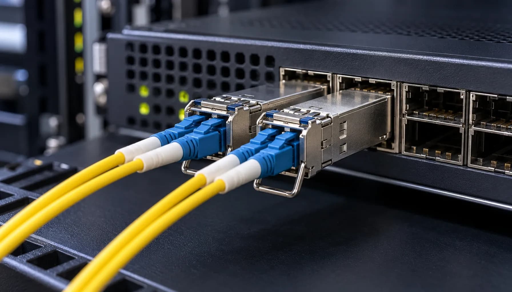
Can RS485 Modbus traffic share the plant Ethernet switch, or should it go over fibre?
Sharing is fine: the gateway converts RS485 to Modbus TCP, and the switch provides VLAN isolation, storm control and control-plane protection. However, the switch does not terminate or bias the RS485 pair — those stay at the field end. For multi-site aggregation or distances beyond 300–400 m, deploy RS485-to-IP or RS485-over-IP gateways with fibre uplinks rather than extending copper.
Key Takeaways
- Audit every RS485 Modbus segment for termination, bias, isolation and topology; measure ~60 Ω across the bus and < 30 mV p-p idle differential noise.
- Bias the segment, not the gateway’s transceiver, so the bus has a defined idle state throughout the inter-poll window.
- Keep one polling master per segment; deploy isolated gateways with fixed, protocol-compliant timing (9,600 bps, 1.5 s timeout, 3.5-character silence).
- Place RS485 gateways on a dedicated access VLAN with storm control, CoPP and errdisable recovery, using a documented Cisco/Nexus, Arista or Juniper profile.
- Commission with a 24-hour capture proving zero phantom frames and a CRC error rate below 0.1% before handing over to SCADA.
Conclusion
Most “Modbus problems” on solar sites are wiring problems wearing a protocol costume: undefined idle state, wrong termination, missing isolation and uncontrolled polling. Specify the bus hardware and the commissioning procedure together, then source isolated gateways, surge protection and field-bus cabling from the Strinex UAE catalogue before the next rooftop installation is energised.