Our Blog
STRINEX advances eco-friendly technologies, reducing fossil fuel reliance and supporting sustainable living. Our mission is to lead renewable energy and sustainable infrastructure through innovation and efficiency.
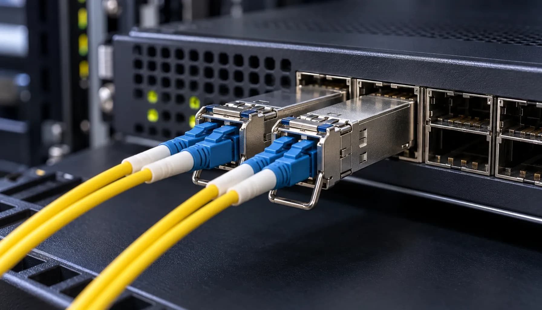
Single-Mode (OS2) vs Multi-Mode (OM3/OM4) Wiring & CLI Verification Cheat-Sheet: Power Budget, OTDR Traces & Vendor Lock Commands for UAE Enterprises
Single-Mode (OS2) vs Multi-Mode (OM3/OM4) Wiring & CLI Verification Cheat-Sheet: Power Budget, OTDR Traces & Vendor Lock Commands for UAE Enterprises In modern UAE enterprise networks, selecting the right fiber optic cabling is crucial for performance, scalability, and cost-efficiency. This article delves into the technical intricacies of Single-Mode OS2 and Multi-Mode OM3/OM4 wiring, providing a comprehensive comparison, power budget analysis, OTDR trace interpretation, and essential CLI commands for Cisco, Arista, and Juniper switches. This guide aims to equip network engineers with the knowledge to make informed decisions and troubleshoot effectively. 1. Single-Mode OS2 vs Multi-Mode OM3/OM4: A Technical Comparison Key Differences in Specifications and Standards When choosing between Single-Mode OS2 and Multi-Mode OM3/OM4, understanding their technical specifications is paramount. The following table provides a detailed comparison: | **Specification** | **Single-Mode OS2** | **Multi-Mode OM3** | **Multi-Mode OM4** | |----------------------------|------------------------------|------------------------------|------------------------------| | **Core Diameter** | 8-10 microns | 50 microns | 50 microns | | **Bandwidth (MHz·km)** | Not applicable | 2000 MHz·km | 4700 MHz·km | | **Distance (10G)** | Up to 10 km | Up to 300 m | Up to 400 m | | **Distance (40G/100G)** | Up to 10 km | Up to 100 m | Up to 150 m | | **Attenuation (dB/km)** | 0.4 dB/km @ 1310 nm | 3.5 dB/km @ 850 nm | 3.5 dB/km @ 850 nm | | **Wavelengths Supported** | 1310 nm, 1550 nm | 850 nm, 1300 nm | 850 nm, 1300 nm | | **Cost per Meter** | Higher | Lower | Lower | | **Common Applications** | Long-haul, high-speed links | Data centers, short-reach | Data centers, short-reach | Key takeaway: Single-Mode OS2 is ideal for long-distance applications due to its lower attenuation and higher bandwidth capacity, while Multi-Mode OM3/OM4 is suitable for short-reach, high-density deployments in data centers. Distance, Loss, and Cost Considerations In UAE enterprise networks, the choice between OS2 and OM3/OM4 often hinges on the required distance and budget constraints. Distance: OS2 can transmit data over much longer distances (up to 10 km) compared to OM3 (up to 300 m) and OM4 (up to 400 m). This makes OS2 the preferred choice for campus networks and metropolitan area networks (MANs). Loss: OS2 exhibits lower attenuation (0.4 dB/km at 1310 nm) compared to OM3/OM4 (3.5 dB/km at 850 nm). This translates to lower signal loss over long distances. Cost: While OS2 cables are more expensive per meter, the overall cost may be justified for long-distance applications. Conversely, OM3/OM4 cables are more cost-effective for short-reach, high-density deployments. For a more detailed analysis of distance, loss, and cost, refer to our previous article: Single-Mode OS2 vs Multi-Mode OM3/OM4: Distance, Loss & Cost for UAE Enterprise Networks . 2. Power Budget Analysis for OS2 and OM3/OM4 Links Understanding Power Budget The power budget is the difference between the transmitter's output power and the receiver's sensitivity. It determines the maximum allowable loss in the fiber link. OS2 Power Budget: Typically, OS2 links have a power budget of around 20 dB for 10G links. This allows for longer distances with minimal signal loss. OM3/OM4 Power Budget: For OM3/OM4, the power budget is typically 2.3 dB for 10G links. This lower budget is due to the higher attenuation at 850 nm. Calculating Power Budget To calculate the power budget, use the following formula: For example, if the transmitter output power is -3 dBm and the receiver sensitivity is -15 dBm, the power budget is: Ensuring Adequate Power Budget When designing fiber links, ensure that the total link loss is within the power budget. The total link loss includes fiber attenuation, connector losses, and splice losses. Key takeaway: Always calculate the power budget to ensure that the fiber link can support the required data rate and distance. 3. OTDR Trace Interpretation for OS2 and OM3/OM4 Links Introduction to OTDR Optical Time-Domain Reflectometer (OTDR) is a crucial tool for testing and troubleshooting fiber optic cables. It measures the return loss and reflection of light pulses to identify faults and measure attenuation. Interpreting OTDR Traces OS2 Traces: OS2 traces typically show a clean, straight line with minimal reflections due to the low attenuation and high bandwidth. Any significant reflections or spikes may indicate a fault or poor connector. OM3/OM4 Traces: OM3/OM4 traces may show more reflections and attenuation due to the higher core diameter and lower bandwidth. However, the overall trace should still be relatively smooth. Common Issues Identified by OTDR Fiber Breaks: A sudden drop in the trace indicates a fiber break. Connector Losses: A spike followed by a drop indicates a connector with high loss. Macro-Bends: A gradual increase in attenuation indicates a macro-bend in the fiber. Key takeaway: Use OTDR traces to identify and locate faults in fiber optic cables, ensuring optimal performance and reliability. 4. Multi-Vendor Switch CLI Configuration Block Cisco, Arista, and Juniper CLI Commands Configuring fiber optic interfaces on multi-vendor switches requires specific commands. Below is a cheat-sheet for Cisco, Arista, and Juniper switches. Cisco Catalyst/Nexus Arista 7050X Juniper QFX Vendor Lock Commands Cisco: Use the transceiver type command to set the appropriate transceiver type. Arista: Use the transceiver type command to set the appropriate transceiver type. Juniper: Use the set interfaces command with the transceiver option to set the appropriate transceiver type. Key takeaway: Use the correct CLI commands to configure fiber optic interfaces on multi-vendor switches, ensuring compatibility and optimal performance. 5. Conclusion and Recommendations Final Recommendations Choose OS2 for Long-Distance Applications: If your network requires long-distance connectivity (e.g., between buildings or campuses), opt for Single-Mode OS2 cables. Use OM3/OM4 for Data Centers: For high-density, short-reach deployments in data centers, Multi-Mode OM3/OM4 cables are more cost-effective and efficient. Perform Power Budget Analysis: Always calculate the power budget to ensure that the fiber link can support the required data rate and distance. Utilize OTDR for Troubleshooting: Use OTDR traces to identify and locate faults in fiber optic cables, ensuring optimal performance and reliability. Configure Correct Transceiver Types: Ensure that the correct transceiver types are configured on multi-vendor switches using the appropriate CLI commands. Additional Resources For more detailed information on fiber optic infrastructure hardware, refer to our comprehensive comparison: Strinex vs FS.com vs Alphabridge: Side-by-Side Single-Mode (OS2) vs Multi-Mode (OM3/OM4) Infrastructure Hardware Comparison . Key takeaway: Selecting the right fiber optic cabling and configuring it correctly is crucial for network performance, reliability, and cost-efficiency. By following this guide, UAE enterprises can make informed decisions about their fiber optic cabling and ensure that their networks are optimized for performance and scalability.
Categories
Popular Tags

Single-Mode (OS2) vs Multi-Mode (OM3/OM4) Wiring & CLI Verification Cheat-Sheet: Power Budget, OTDR Traces & Vendor Lock Commands for UAE Enterprises
Single-Mode (OS2) vs Multi-Mode (OM3/OM4) Wiring & CLI Verification Cheat-Sheet: Power Budget, OTDR Traces & Vendor Lock Commands for UAE Enterprises In modern UAE enterprise networks, selecting the right fiber optic cabling is crucial for performance, scalability, and cost-efficiency. This article delves into the technical intricacies of Single-Mode OS2 and Multi-Mode OM3/OM4 wiring, providing a comprehensive comparison, power budget analysis, OTDR trace interpretation, and essential CLI commands for Cisco, Arista, and Juniper switches. This guide aims to equip network engineers with the knowledge to make informed decisions and troubleshoot effectively. 1. Single-Mode OS2 vs Multi-Mode OM3/OM4: A Technical Comparison Key Differences in Specifications and Standards When choosing between Single-Mode OS2 and Multi-Mode OM3/OM4, understanding their technical specifications is paramount. The following table provides a detailed comparison: | **Specification** | **Single-Mode OS2** | **Multi-Mode OM3** | **Multi-Mode OM4** | |----------------------------|------------------------------|------------------------------|------------------------------| | **Core Diameter** | 8-10 microns | 50 microns | 50 microns | | **Bandwidth (MHz·km)** | Not applicable | 2000 MHz·km | 4700 MHz·km | | **Distance (10G)** | Up to 10 km | Up to 300 m | Up to 400 m | | **Distance (40G/100G)** | Up to 10 km | Up to 100 m | Up to 150 m | | **Attenuation (dB/km)** | 0.4 dB/km @ 1310 nm | 3.5 dB/km @ 850 nm | 3.5 dB/km @ 850 nm | | **Wavelengths Supported** | 1310 nm, 1550 nm | 850 nm, 1300 nm | 850 nm, 1300 nm | | **Cost per Meter** | Higher | Lower | Lower | | **Common Applications** | Long-haul, high-speed links | Data centers, short-reach | Data centers, short-reach | Key takeaway: Single-Mode OS2 is ideal for long-distance applications due to its lower attenuation and higher bandwidth capacity, while Multi-Mode OM3/OM4 is suitable for short-reach, high-density deployments in data centers. Distance, Loss, and Cost Considerations In UAE enterprise networks, the choice between OS2 and OM3/OM4 often hinges on the required distance and budget constraints. Distance: OS2 can transmit data over much longer distances (up to 10 km) compared to OM3 (up to 300 m) and OM4 (up to 400 m). This makes OS2 the preferred choice for campus networks and metropolitan area networks (MANs). Loss: OS2 exhibits lower attenuation (0.4 dB/km at 1310 nm) compared to OM3/OM4 (3.5 dB/km at 850 nm). This translates to lower signal loss over long distances. Cost: While OS2 cables are more expensive per meter, the overall cost may be justified for long-distance applications. Conversely, OM3/OM4 cables are more cost-effective for short-reach, high-density deployments. For a more detailed analysis of distance, loss, and cost, refer to our previous article: Single-Mode OS2 vs Multi-Mode OM3/OM4: Distance, Loss & Cost for UAE Enterprise Networks . 2. Power Budget Analysis for OS2 and OM3/OM4 Links Understanding Power Budget The power budget is the difference between the transmitter's output power and the receiver's sensitivity. It determines the maximum allowable loss in the fiber link. OS2 Power Budget: Typically, OS2 links have a power budget of around 20 dB for 10G links. This allows for longer distances with minimal signal loss. OM3/OM4 Power Budget: For OM3/OM4, the power budget is typically 2.3 dB for 10G links. This lower budget is due to the higher attenuation at 850 nm. Calculating Power Budget To calculate the power budget, use the following formula: For example, if the transmitter output power is -3 dBm and the receiver sensitivity is -15 dBm, the power budget is: Ensuring Adequate Power Budget When designing fiber links, ensure that the total link loss is within the power budget. The total link loss includes fiber attenuation, connector losses, and splice losses. Key takeaway: Always calculate the power budget to ensure that the fiber link can support the required data rate and distance. 3. OTDR Trace Interpretation for OS2 and OM3/OM4 Links Introduction to OTDR Optical Time-Domain Reflectometer (OTDR) is a crucial tool for testing and troubleshooting fiber optic cables. It measures the return loss and reflection of light pulses to identify faults and measure attenuation. Interpreting OTDR Traces OS2 Traces: OS2 traces typically show a clean, straight line with minimal reflections due to the low attenuation and high bandwidth. Any significant reflections or spikes may indicate a fault or poor connector. OM3/OM4 Traces: OM3/OM4 traces may show more reflections and attenuation due to the higher core diameter and lower bandwidth. However, the overall trace should still be relatively smooth. Common Issues Identified by OTDR Fiber Breaks: A sudden drop in the trace indicates a fiber break. Connector Losses: A spike followed by a drop indicates a connector with high loss. Macro-Bends: A gradual increase in attenuation indicates a macro-bend in the fiber. Key takeaway: Use OTDR traces to identify and locate faults in fiber optic cables, ensuring optimal performance and reliability. 4. Multi-Vendor Switch CLI Configuration Block Cisco, Arista, and Juniper CLI Commands Configuring fiber optic interfaces on multi-vendor switches requires specific commands. Below is a cheat-sheet for Cisco, Arista, and Juniper switches. Cisco Catalyst/Nexus Arista 7050X Juniper QFX Vendor Lock Commands Cisco: Use the transceiver type command to set the appropriate transceiver type. Arista: Use the transceiver type command to set the appropriate transceiver type. Juniper: Use the set interfaces command with the transceiver option to set the appropriate transceiver type. Key takeaway: Use the correct CLI commands to configure fiber optic interfaces on multi-vendor switches, ensuring compatibility and optimal performance. 5. Conclusion and Recommendations Final Recommendations Choose OS2 for Long-Distance Applications: If your network requires long-distance connectivity (e.g., between buildings or campuses), opt for Single-Mode OS2 cables. Use OM3/OM4 for Data Centers: For high-density, short-reach deployments in data centers, Multi-Mode OM3/OM4 cables are more cost-effective and efficient. Perform Power Budget Analysis: Always calculate the power budget to ensure that the fiber link can support the required data rate and distance. Utilize OTDR for Troubleshooting: Use OTDR traces to identify and locate faults in fiber optic cables, ensuring optimal performance and reliability. Configure Correct Transceiver Types: Ensure that the correct transceiver types are configured on multi-vendor switches using the appropriate CLI commands. Additional Resources For more detailed information on fiber optic infrastructure hardware, refer to our comprehensive comparison: Strinex vs FS.com vs Alphabridge: Side-by-Side Single-Mode (OS2) vs Multi-Mode (OM3/OM4) Infrastructure Hardware Comparison . Key takeaway: Selecting the right fiber optic cabling and configuring it correctly is crucial for network performance, reliability, and cost-efficiency. By following this guide, UAE enterprises can make informed decisions about their fiber optic cabling and ensure that their networks are optimized for performance and scalability.
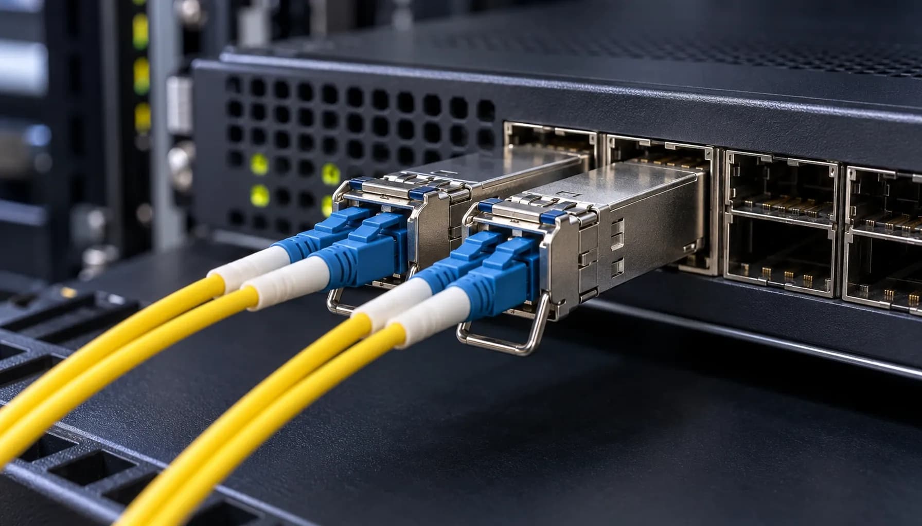
Strinex vs FS.com vs Alphabridge: Side-by-Side Single-Mode (OS2) vs Multi-Mode (OM3/OM4) Infrastructure Hardware Comparison
Strinex vs FS.com vs Alphabridge: Side-by-Side Single-Mode (OS2) vs Multi-Mode (OM3/OM4) Infrastructure Hardware Comparison Introduction: Choosing the Right Fiber Infrastructure for Modern Networks In today's data center and enterprise environments, selecting the appropriate fiber infrastructure is critical for performance, scalability, and cost-effectiveness. The choice between single-mode (OS2) and multi-mode (OM3/OM4) fiber often dictates the network's capabilities and future-proofing. This article provides a detailed comparison of infrastructure hardware from Strinex, FS.com, and Alphabridge, focusing on real-world deployment scenarios with Cisco Catalyst/Nexus, Arista 7050X, and Juniper QFX switches. 1. Distance and Loss: Single-Mode OS2 vs Multi-Mode OM3/OM4 Single-Mode OS2: Long Haul and Low Loss Single-mode OS2 fiber is designed for long-distance transmission with minimal loss. It supports distances up to 10 km and even beyond, depending on the transceiver type and power budget. The typical attenuation for OS2 fiber is around 0.4 dB/km at 1310 nm and 0.25 dB/km at 1550 nm. Advantages: Long Distance Support: Ideal for campus networks, metropolitan area networks (MANs), and inter-data center links. Lower Attenuation: Less signal loss over long distances compared to multi-mode fiber. Higher Bandwidth: Supports higher data rates without significant degradation. Disadvantages: Higher Cost: OS2 transceivers and infrastructure are generally more expensive. Complex Installation: Requires precise alignment and more expensive connectors. Multi-Mode OM3/OM4: Short to Medium Range Multi-mode OM3 and OM4 fibers are optimized for shorter distances, typically up to 300 meters for OM3 and 550 meters for OM4 at 10 Gbps. The attenuation for OM3 is around 3 dB/km at 850 nm, while OM4 has an attenuation of approximately 2.3 dB/km at the same wavelength. Advantages: Cost-Effective: Lower cost for transceivers and infrastructure. Ease of Installation: More forgiving in terms of alignment and connector quality. Sufficient for Most Enterprise Needs: Adequate for data centers and enterprise LANs. Disadvantages: Shorter Distance Support: Limited to shorter spans compared to single-mode. Higher Attenuation: More signal loss over distance. Comparative Table: Distance and Loss | Specification | Single-Mode OS2 | Multi-Mode OM3 | Multi-Mode OM4 | |---------------------|-----------------|----------------|-----------------| | **Distance (10 Gbps)** | Up to 10 km | Up to 300 m | Up to 550 m | | **Attenuation (dB/km)** | 0.4 @ 1310 nm | 3.0 @ 850 nm | 2.3 @ 850 nm | | **Bandwidth (MHz·km)** | N/A | 2000 | 4700 | | **Typical Application** | Long-haul, MAN | Data centers, LANs | Data centers, LANs | Key takeaway: Single-mode OS2 is best for long-distance, high-bandwidth applications, while multi-mode OM3/OM4 is suitable for shorter distances and cost-sensitive environments. 2. Cost Comparison: Infrastructure and Transceivers Single-Mode OS2: Higher Initial Costs The initial investment for single-mode OS2 infrastructure is higher due to the cost of fiber, connectors, and transceivers. For instance, a typical OS2 SFP+ transceiver can cost between $50 to $100, whereas a multi-mode OM4 SFP+ transceiver may cost around $20 to $50. Multi-Mode OM3/OM4: Economical for Short to Medium Ranges Multi-mode OM3/OM4 infrastructure offers a more economical solution for short to medium range applications. The cost of fiber and connectors is lower, and transceivers are generally less expensive. However, the cost savings can be offset by the need for more frequent repeaters or additional access points in larger networks. Cost Comparison Table | Component | Single-Mode OS2 | Multi-Mode OM3 | Multi-Mode OM4 | |----------------------|-----------------|----------------|-----------------| | **Fiber Cost per Meter** | $0.50 | $0.30 | $0.35 | | **Connector Cost per Pair** | $5.00 | $3.00 | $3.50 | | **SFP+ Transceiver Cost** | $70 | $30 | $40 | | **Total Cost for 1 km Link (10 Gbps)** | $1,200 | $600 | $700 | Key takeaway: While single-mode OS2 has higher upfront costs, it may be more cost-effective for long-distance applications due to fewer repeaters and less signal loss. 3. Multi-Vendor Switch Compatibility and CLI Configuration Cisco, Arista, and Juniper Compatibility All three vendors—Cisco, Arista, and Juniper—support both single-mode OS2 and multi-mode OM3/OM4 transceivers. However, it is crucial to ensure that the transceivers are compatible with the specific switch model and firmware version. Cisco Configuration Example Arista Configuration Example Juniper Configuration Example Key takeaway: Ensure transceiver compatibility with the switch model and firmware version. Use the correct CLI commands to configure the interface for single-mode or multi-mode operation. 4. Standards and Compliance Industry Standards Both single-mode OS2 and multi-mode OM3/OM4 fibers adhere to industry standards such as ITU-T G.652 for OS2 and ISO/IEC 11801 for OM3/OM4. These standards ensure interoperability and performance across different vendors and applications. Compliance and Testing OS2 Compliance: Requires compliance with ITU-T G.652 standards, ensuring low dispersion and attenuation. OM3/OM4 Compliance: Requires compliance with ISO/IEC 11801 standards, ensuring high bandwidth and low attenuation at 850 nm. Testing and Certification Proper testing and certification are essential for ensuring the performance and reliability of the fiber infrastructure. Tools such as OTDR (Optical Time-Domain Reflectometer) and light source and power meter are commonly used for testing. Key takeaway: Adherence to industry standards and proper testing are critical for ensuring the performance and reliability of the fiber infrastructure. Conclusion: Making the Right Choice for Your Network Selecting between single-mode OS2 and multi-mode OM3/OM4 fiber depends on the specific needs of your network, including distance, bandwidth, and cost considerations. Single-mode OS2 is ideal for long-distance, high-bandwidth applications, while multi-mode OM3/OM4 offers a cost-effective solution for shorter distances. Final Recommendations For Long-Distance, High-Bandwidth Needs: Choose single-mode OS2. For Cost-Effective, Short to Medium Range Applications: Choose multi-mode OM3/OM4. By understanding the differences in distance, loss, cost, and compatibility, you can make an informed decision that aligns with your network requirements and budget. Key takeaway: The choice between single-mode OS2 and multi-mode OM3/OM4 should be based on a comprehensive analysis of your network's specific needs, including distance, bandwidth, and cost. --- This article provides a detailed comparison of single-mode OS2 and multi-mode OM3/OM4 fiber infrastructure, offering actionable insights for network engineers and decision-makers. For more in-depth information on related topics, check out our other articles: Single-Mode OS2 vs Multi-Mode OM3/OM4: Distance, Loss & Cost for UAE Enterprise Networks Third-Party SFP Module Coding & EEPROM Programming: The Complete UAE Enterprise Network Guide (2026) 100G QSFP28 Optical Form Factors: SR4 vs LR4 vs CWDM4 vs PSM4 Compared: The Complete UAE Enterprise Procurement Guide (2026) BiDi SFP+ Transceivers: Doubling Fiber Capacity over Single Strand (WDM Simplex): The Complete UAE Engineering Guide (2026)
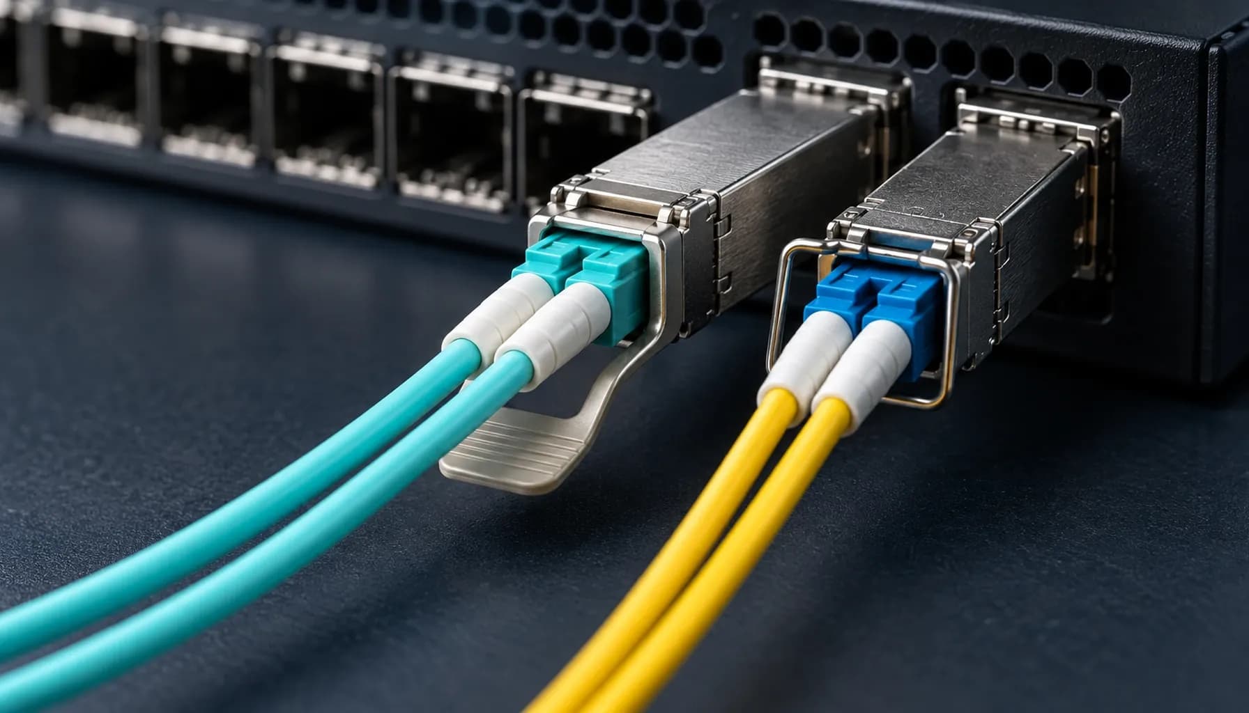
Single-Mode OS2 vs Multi-Mode OM3/OM4: Distance, Loss & Cost for UAE Enterprise Networks
Dubai Internet City data centres and Abu Dhabi industrial SCADA estates expose the same mistake in different forms: teams choose fibre by cable price, then discover that optics or the route makes the decision expensive. Start with the installed plant, the longest permanent link, and the optical budget. OS2 is the default for new campus, metro, and building-to-building routes in the UAE. OM3 and OM4 still make sense in contained equipment rooms with short, predictable 850 nm links. They are different transmission systems with different failure modes and cost curves. Operating principles, reach and loss budget OS2 single-mode fibre has an approximately 9 µm core and normally carries 1310 nm or 1550 nm optics. Its low attenuation and lack of modal dispersion make it the rational choice beyond the data-hall boundary. OM3 and OM4 use a 50 µm core and 850 nm VCSEL optics, where modal bandwidth sets practical reach. Use 300 m for OM3 and 400 m for OM4, subject to the installed channel class and vendor data sheet. A 10GBASE-LR optic is specified for 10 km over OS2. Build the budget before ordering optics: $P_{\text{budget}} = P_{\text{Tx\_min}} - S_{\text{Rx\_sens}}$. Deduct fibre attenuation, connector pairs, splices, and a margin for dirt, ageing, and the next patch panel. For a new OS2 backbone, pair the route with a compatible Strinex 10G/25G optical transceiver only after confirming wavelength, reach, connector type, and host coding. Comparison matrix | Parameter | Strinex Alpha Bridge | FS.com Equivalent | Cisco OEM | Generic / Refurbished | | :--- | :--- | :--- | :--- | :--- | | OS2 long-reach option | Verify LR or 20 km SKU, 1310 nm | Select exact LR/ER variant | Qualified LR optic | Validate label and test report | | OM3/OM4 short-reach option | Verify SR SKU, 850 nm | Select exact SR variant | Qualified SR optic | Confirm actual wavelength | | Host coding | Confirm Cisco, Juniper, Arista or MikroTik target | Order coded variant | Native coding | Often unknown or locked | | DDM telemetry | Check SFF-8472 support | Check module data sheet | Platform dependent | Frequently inconsistent | | UAE supply and warranty | Local stock and support | Confirm lead time and return path | Confirm channel stock | Verify provenance and warranty | A brand name does not repair a mismatched wavelength or an exhausted loss budget. Cisco OEM can be a conservative procurement path, but it does not remove the need to validate DOM readings, fibre type, and the switch release in use. Interoperability and host validation Cisco, Juniper, Arista, and MikroTik ports need matching speed, wavelength, connector, and fibre mode at both ends. Verify SFF-8431 host interface and SFF-8472 diagnostic support before treating a module as interchangeable. Cisco and Juniper platforms may enforce vendor EEPROM checks; a permissive port is not proof of a healthy link. Record the host model, release, optic part and serial number, DDM thresholds, and measured receive power during staging. For coding constraints and EEPROM checks, see Third-Party SFP Module Coding & EEPROM Programming . Use the SFF-8472 DOM/DDM diagnostics field guide to interpret telemetry against the module data sheet. Field deployment and maintenance Treat bend radius as an optical requirement. Hold a minimum installed bend radius above $30\text{ mm}$ for patch leads unless the manufacturer specifies a larger limit. Inspect every ferrule before mating and follow IEC 61300-3-35: dry clean first, use wet-to-dry cleaning when contamination persists, inspect again, and cap exposed connectors. Recommended diagnostic utilities and testing tools Fluke Networks FiberInspector Pro checks ferrule end faces before a connector consumes the link budget. EXFO MaxTester OTDR locates splice, connector, and bend events on OS2 routes. VIAVI SmartClass Fiber OLP-88 measures end-to-end insertion loss and optical power for acceptance testing. Frequently asked questions Should a new UAE campus backbone use OS2? Yes, unless the route is permanently confined to short data-hall links with a clear OM3 or OM4 standard. OS2 preserves options for 10 km LR optics and later capacity changes without replacing the cable plant. Specify the optic reach for the actual route and retain usable margin. Is OM4 always better than OM3? OM4 offers more effective modal bandwidth and a longer 10GBASE-SR channel than OM3. It does not turn 850 nm multimode into a campus technology or compensate for dirty connectors. Use it where the extra reach or high-speed roadmap has documented value. Can a Cisco switch use a third-party optic? Many Cisco models can, subject to platform policy, release, coding, and support rules. Stage the exact optic in the intended port and confirm link, DOM, alarms, and error counters. Keep an approved spare with identical coding, not merely the same wavelength. How much loss margin should a fibre design retain? Calculate every fixed loss first, then reserve a practical margin for contamination, ageing, and future cross-connects. The exact allowance depends on the optic specification and maintenance regime. A design that only passes on paper will fail first during a dusty maintenance window. Why does a link fail after an apparently clean installation? Most short fibre faults come from contaminated ferrules, reversed polarity, tight bends, or incompatible optics. Inspect both ends and compare transmit and receive power with the module data sheet. If those checks pass, use insertion-loss testing or OTDR traces to isolate the event. UAE selection checklist Choose OS2 for backbone, campus, and inter-building routes; use OM3 or OM4 for short controlled data-centre channels. Calculate the optical budget and deduct every connector, splice, fibre kilometre, and engineering margin. Validate optic, host coding, firmware, DOM thresholds, and receive power before dispatch. Keep patch-lead bends above $30\text{ mm}$ and follow IEC 61300-3-35 cleaning practice. Conclusion and local UAE procurement OS2 is the sensible long-life cable plant for UAE backbone work; OM3 and OM4 earn their place in short, dense equipment-room links. Strinex holds local Dubai stock for selected optical modules and can support same-day dispatch where stock and order cut-off permit. Review the live 10G/25G optical transceiver range and match the module to the tested host and measured fibre channel.
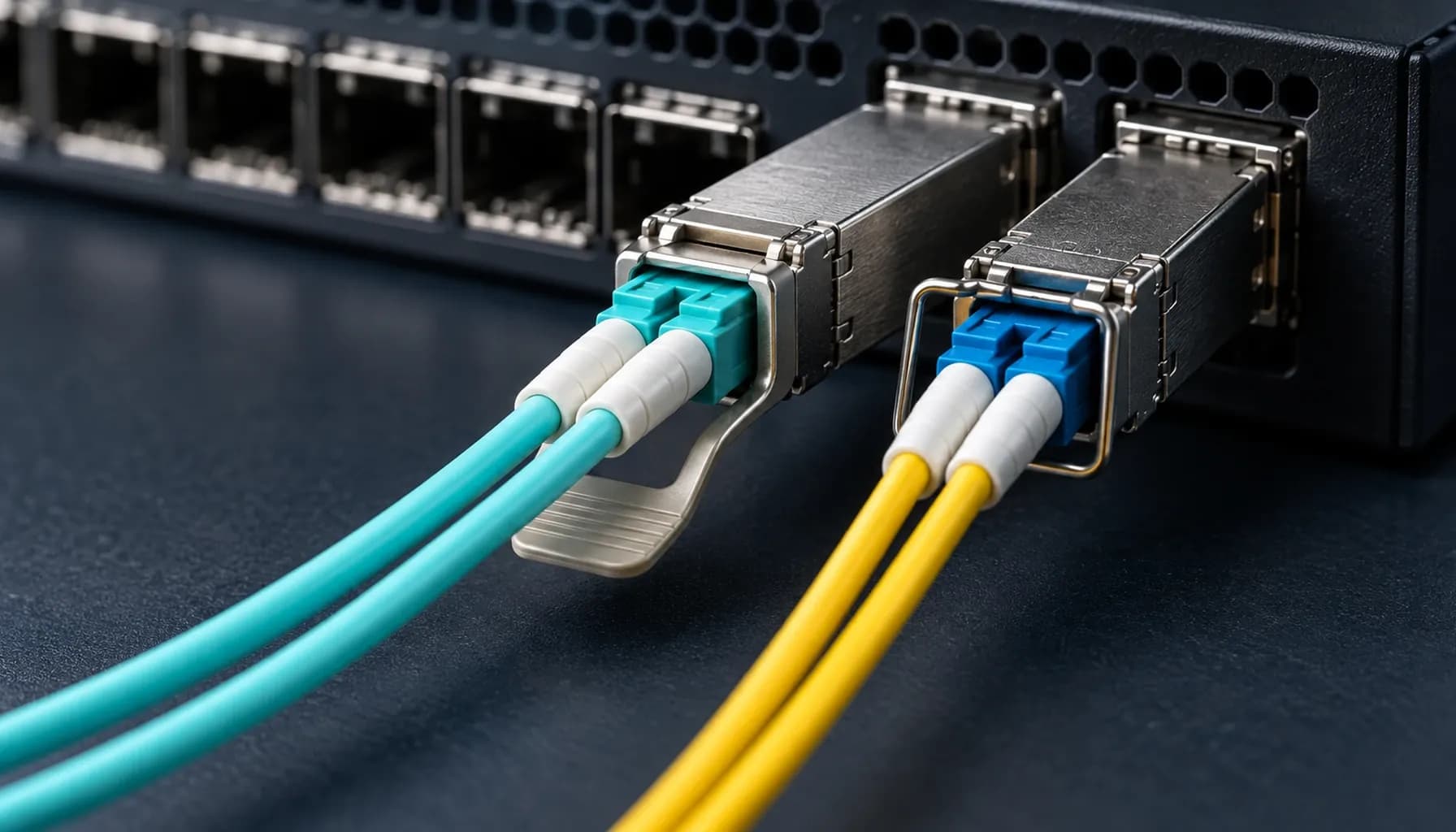
Third-Party SFP Module Coding & EEPROM Programming: The Complete UAE Enterprise Network Guide (2026)
Introduction A rejected optic at 02:00 is rarely an optical problem. In Dubai Internet City data centres, it is usually a host-policy problem: the switch reads the module EEPROM, finds a vendor name or part number it does not expect, then throws a warning or disables the port. That is why a cheap, unqualified optic becomes expensive during a maintenance window. Third-party optics are a sound engineering choice when they are built to the relevant MSA and IEEE requirements, coded for the host, and tested in the actual line card. They are not a licence to mix unknown modules into a production fabric. Treat coding, diagnostics and traceability as part of the optic specification, especially on high-density 10G and 25G cards and in Abu Dhabi industrial SCADA networks where a marginal link can stop useful work. Technical operating principles and power budgets An SFP, SFP+ or SFP28 module exposes identification and diagnostic data through a serial EEPROM. The host reads fields such as connector type, nominal wavelength, vendor name, part number, serial number and supported signalling rate. Modern modules also expose DOM/DDM telemetry: transmit power, receive power, temperature, voltage and laser bias current. The EEPROM does not change the physics of the optic; it tells the host what it is looking at. Coding should therefore match the intended host family, not merely a vendor label. Confirm the exact switch OS, line-card revision and supported optic class before purchase. A Cisco-coded 10GBASE-SR module may identify cleanly in a Cisco port but still needs an optical and thermal check. For active link monitoring, use the thresholds discussed in our SFF-8472 DOM/DDM diagnostics field guide , rather than treating a green link LED as proof of health. Start the optical calculation with the available power budget: $P_{\text{budget}} = P_{\text{Tx\_min}} - S_{\text{Rx\_sens}}$ Then subtract connector loss, fibre attenuation, splice loss and a sensible operational margin. A 10G SR link on OM3 may work at a short patching distance, but it is the wrong answer for a building-to-building run on single-mode fibre. For common 10G and 25G links, Strinex 10G/25G optical transceivers give the starting point; select SR, LR or another optic family from the cable plant and loss budget, not from the port shape. Comparison matrix | Parameter | Strinex Alpha Bridge | FS.com Equivalent | Cisco OEM | Generic / Refurbished | | :--- | :--- | :--- | :--- | :--- | | Host coding | Ordered for the target host and checked before dispatch | Select host coding at order | Native Cisco identity | Often generic or undocumented | | Traceability | Part and serial recorded for support | Varies by order process | Full OEM traceability | Serial history may be absent | | DOM/DDM | SFF-8472 telemetry and threshold review | Confirm by selected SKU | Supported on qualified model | Readings can be incomplete | | Warranty and replacement | Local support path and Dubai stock | Confirm regional return path | OEM RMA process | Seller-dependent | | Procurement decision | Best fit when coding and local response matter | Viable after host validation | Use where OEM support policy requires it | Avoid for critical links | The table is deliberately less flattering to refurbished optics. A reused module can pass traffic today while carrying unknown laser hours, questionable EEPROM history, or a contaminated ferrule. That risk belongs in a lab or a low-impact spare pool, not in a core uplink. Interoperability and host validation Multi-vendor compatibility is practical, but it demands a disciplined acceptance test. Cisco, Juniper, Arista and MikroTik each expose transceiver inventory and diagnostics differently, and some platforms alert on unsupported optics even when they continue forwarding traffic. Never rely on a copied command from an internet forum to override a host check. Review the vendor documentation and the customer's support policy first; an override can affect future TAC support. Validate every new optic on the intended switch model and software release. Check module recognition, negotiated speed, DOM values, error counters and link stability under traffic. Record the coding profile in the asset system. This matters more on a leaf switch full of SFP28 ports, where a batch mismatch can turn a straightforward change into a rack-wide incident. If the design is moving to 100G uplinks, compare the fibre and lane requirements in our QSFP28 form-factor guide before standardising the access layer. Field deployment and maintenance Most intermittent optic faults arrive at the patch panel, not in the EEPROM. Keep the fibre bend radius above $30\text{ mm}$ unless the cable manufacturer specifies a larger limit. Do not compress a patch lead behind a crowded line card, and do not use the latch as a handle for cable dressing. Adopt an IEC 61300-3-35 cleaning routine: inspect the ferrule, clean it with an approved dry method, inspect again, then connect it. Repeat that sequence for both ends of the link and for any adapter that has been exposed during the change. Dust, oil and a small scratch can consume the margin that looked comfortable on the spreadsheet. Capture baseline DOM values after commissioning and compare them during maintenance. A slow receive-power decline is useful evidence; it tells you where to inspect before the link starts flapping in the middle of a shift. Recommended diagnostic utilities and testing tools Fluke Networks FI-7000 FiberInspector Pro checks ferrule cleanliness and damage before an optic is blamed. EXFO FTBx-735C OTDR locates fibre events and helps separate a cable fault from a module fault. VIAVI SmartClass Fiber OLTS measures insertion loss against the planned link budget. Frequently asked questions Does EEPROM coding change the optical performance of an SFP module? No. EEPROM coding changes the identity and capability information the host reads; it does not change wavelength, launch power or receiver sensitivity. The physical module must still meet its data-sheet specification. Test coding and optics as separate acceptance items. Can Cisco, Juniper, Arista and MikroTik use the same third-party optic? Sometimes, but do not assume it. The optic hardware can be the same while the EEPROM profile differs by host. Order the correct coding profile, then validate it on the exact switch and software release before production deployment. Should we disable unsupported-transceiver warnings? Only after the customer accepts the support implication and the module passes validation. A warning can be useful evidence of an unsupported inventory change. Suppressing it should not replace a documented qualification process. How much optical margin should a UAE enterprise link carry? Use the module data sheet and measured channel loss, then retain enough margin for contamination, temperature and future patching changes. There is no universal number that fits every optic class. Short links can fail with a dirty connector, while long links need careful attenuation accounting. Are refurbished SFP modules suitable for core links? They are a poor default for core and industrial links because their operating history and EEPROM provenance may be unclear. Use new, coded modules with a defined warranty where downtime carries operational cost. Refurbished stock can make sense only after inspection and lab testing for a non-critical spare role. Key takeaways and UAE selection checklist Match the optic family to the installed fibre and measured loss budget; do not select SR or LR by price alone. Specify the target host coding, switch software version and port type on the purchase request. Capture baseline DOM/DDM values after commissioning and investigate threshold drift before a link fails. Keep bend radius above $30\text{ mm}$ and follow IEC 61300-3-35 inspection and cleaning practice. Pay for traceability and warranty on links that carry core, storage or SCADA traffic. Conclusion and local UAE procurement Third-party SFP coding works when it is treated as controlled configuration, not a shortcut around a vendor warning. Specify the host, calculate the optical budget, validate the module in the destination platform and preserve the test record. That process gives a UAE operations team a supportable network instead of a drawer of anonymous optics. For urgent replacements, local Dubai stock and same-day dispatch matter as much as the module price. Review the live Strinex 10G/25G optical transceiver product page for the current option, then provide the switch model, port speed, fibre type and required reach when requesting coded stock.