
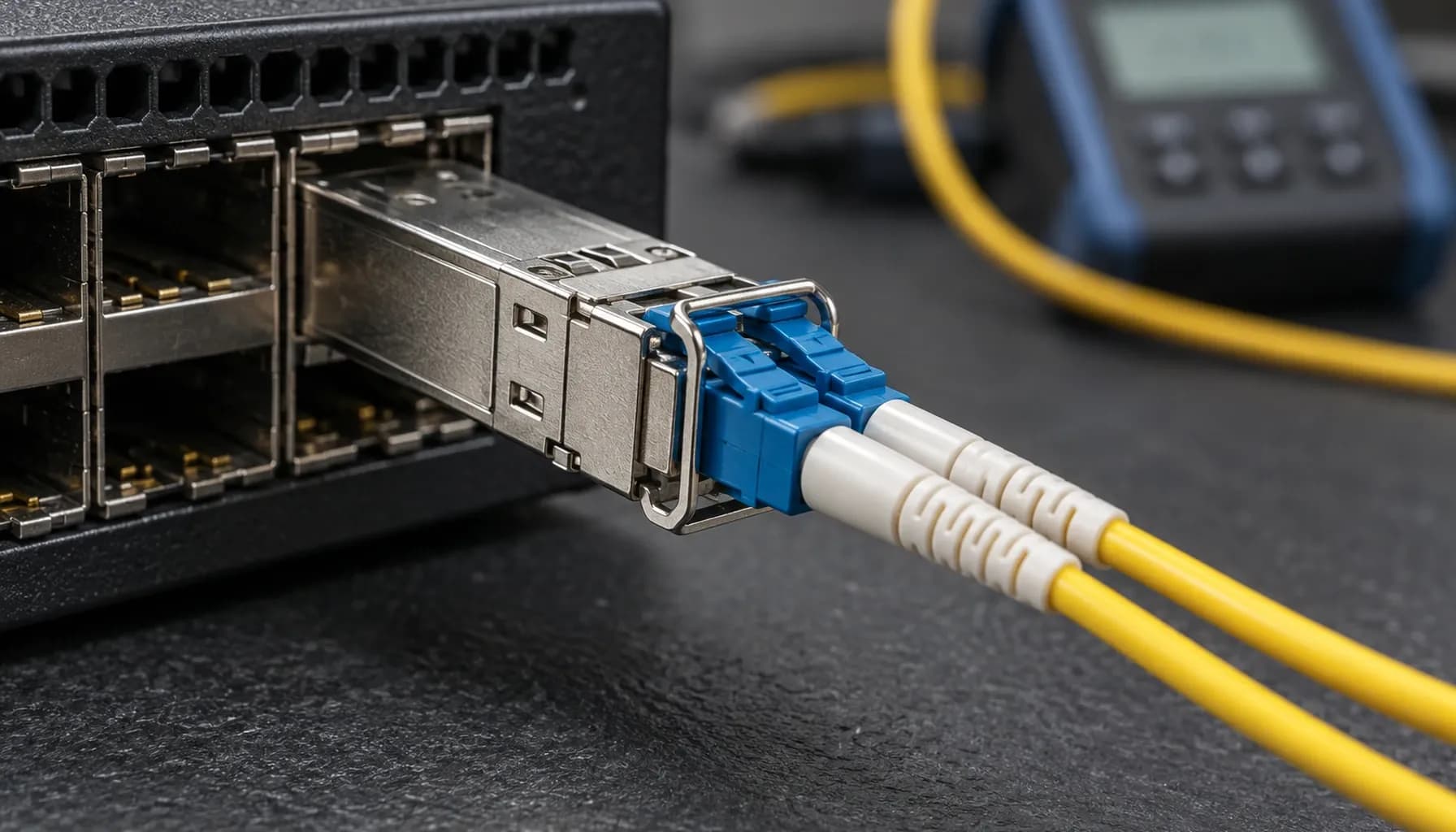
The correct fibre decision is made from the measured channel and its growth horizon—not from the lowest transceiver line price. This single-mode (OS2) vs multi-mode (OM3/OM4) infrastructure enterprise guide UAE sets the boundary clearly: use OM3/OM4 for short, contained 850 nm data-centre channels that already qualify; build OS2 where distance, campus reach, WDM options, or a long refresh cycle govern the architecture.
For new inter-building, industrial, and large data-centre backbone routes in the UAE, OS2 is the default. Multimode remains efficient inside a defined equipment room.
Optical physics, reach, and the loss budget
OM3 and OM4 are 50/125 µm laser-optimised multimode fibres, normally paired with 850 nm VCSEL optics. At 10 GbE, 10GBASE-SR is commonly designed for 300 m on OM3 and 400 m on OM4. OS2 is 9/125 µm single-mode fibre, normally paired with 1310 nm LR optics; 10GBASE-LR is commonly specified to 10 km on a compliant G.652 channel. These are application limits, not a substitute for acceptance testing.
The governing calculation is $P_{budget}=P_{Tx_min}-S_{Rx_sens}$. Available budget must exceed fibre attenuation, connector loss, splice loss, patching loss and a design reserve. Retain at least 3 dB of safety margin where the application budget permits. A short OS2 LR link also needs an overload check; a receiver can be too strongly illuminated even when the budget looks generous.
For an in-rack or same-hall 10 GbE channel, the Alpha Bridge ASFP-10G-SR 10G SFP+ optical transceiver is a correctly matched 850 nm, LC-duplex multimode option with a stated 300 m reach and DDM. Do not install it on OS2 simply because the connector fits.
DDM/DOM provides the operational evidence after commissioning. SFF-8472-capable modules expose diagnostics on the two-wire serial interface, conventionally at address 0xA2: temperature, supply voltage, laser bias, Tx power, Rx power, thresholds and flags. Trend both ends. A stable link state is not proof that remaining optical margin is healthy.
**Key takeaway:** Select the fibre and optic as one optical system, then approve the route only after measured loss is below the calculated budget with reserve.
Comparison matrix for high-density infrastructure
| Parameter | Strinex Alpha Bridge | FS.com Equivalent | Cisco OEM | Generic / Refurbished |
|---|---|---|---|---|
| Data Rate / Power Rating | 10G SR; 3.3 V, low-power SFP+ class | 10G SR class; verify exact SKU | 10G SR class; exact PID governs | Varies; label is insufficient |
| Wavelength / Fiber Type | 850 nm, OM3/OM4 MMF | Usually 850 nm, OM3/OM4 MMF | 850 nm SR or 1310 nm LR by PID | May be mismatched or undocumented |
| Max Reach / Range | Stated 300 m for ASFP-10G-SR | SKU-specific; validate | Application/PID-specific | Must be tested, not assumed |
| DDM / DOM Telemetry | DDM stated | SKU-specific | Platform/PID-specific | Often inconsistent |
| Switch Compatibility | MSA basis; validate host policy | Coding and host policy matter | Native supported matrix | Highest interoperability risk |
| UAE Delivery Time | Ex-stock Dubai, same-day dispatch when available | Typically 4–7 days overseas | Depends on authorised stock | Variable local availability |
| Regional Warranty | Local 5-year product warranty stated | Seller-dependent | OEM support contract dependent | Often limited or unclear |
Local replacement stock reduces repair time when a line-card optic fails in a change window. The Strinex 10G/25G Optical Transceivers listing is a starting point for SR-class stock, but final selection follows the host interface, fibre type, temperature class and measured channel.
Multi-vendor switch compatibility and interoperability
MSA electrical compliance is necessary but not sufficient. SFF-8431 defines the SFP+ electrical interface, while SFF-8472 defines diagnostic management information. The module EEPROM identifies its capabilities and vendor coding; the host reads it and may enforce a platform-specific policy. Cisco Catalyst and Nexus, Juniper EX/QFX, Arista 7050SX, and MikroTik RouterOS therefore need a lab validation with the exact software release and port mode before production rollout.
Check speed negotiation, FEC where applicable, breakout configuration, supported optical power, and vendor-optic enforcement separately. An electrically accepted module can still fail because the port speed or fibre polarity is wrong. Use SFF-8472 DOM/DDM Diagnostics: Reading Tx/Rx Power, Bias & Temperature on SFP Modules (2026): capture the exact part number, flags, and readings from both ends before declaring an optic defective.
Avoid blanket “third-party optic” assumptions. Establish one approved module pair per switch family, retain the compatibility evidence, and keep an identical validated spare for each critical site.
Field deployment, insertion loss, and maintenance
Maintain a bend radius greater than 30 mm unless the cable assembly permits less. Keep service loops restrained, use correct LC duplex polarity, and label fibre type and endpoint. Follow the connector geometry specified for the installed system.
Contamination remains the most common avoidable loss source. Apply IEC 61300-3-35 discipline: inspect, dry-clean, inspect again, then mate. Never touch an LC ferrule or clean a connector by blowing on it. After any repair, validate the route with an optical power meter against the launch power and receiver requirements; use an OLTS or OTDR where the fault domain includes the installed cable plant, splices, or unexplained events.
Recommended Diagnostic Utilities & Testing Tools
Use a hierarchy: inspect the endface, confirm polarity and optic identity, read DOM at both endpoints, then measure insertion loss before escalating to trace analysis. This sequence prevents a contaminated patch lead from becoming an unnecessary transceiver replacement.
- Fluke Networks FiberInspector Pro inspects LC endfaces so contamination is found before mating.
- Fluke Networks CertiFiber Pro OLTS measures loss and length against a documented fibre-channel standard.
- EXFO MaxTester OTDR locates events, bends, and splice anomalies on longer OS2 routes.
Frequently asked questions
Should a new UAE data-centre backbone use OS2?
Yes, OS2 is normally the stronger default for a new backbone. It supports long reaches and future optical application choices without replacing the permanent cable plant. Use measured attenuation and expected port speeds to select the eventual transceiver class.
Is OM4 always better than OM3?
No, OM4 is not automatically a better installed channel. Its reach advantage matters only when the active application and route length need it. Existing qualified OM3 remains appropriate for compliant short SR links.
Can an SR SFP+ module operate over OS2?
No, an 850 nm SR module is designed for multimode fibre, not OS2 single-mode fibre. The LC connector compatibility is mechanical only. Use a correctly specified LR or other single-mode application at both ends.
How much optical margin should the design retain?
Keep at least 3 dB where the application budget allows it. That reserve absorbs connector ageing, maintenance variation, and modest channel changes. It does not remove the need to check receiver overload on short single-mode links.
Does DOM replace an optical power-meter test?
No, DOM is operational telemetry rather than calibrated channel certification. It is valuable for trending Tx, Rx, bias, voltage, and temperature against a baseline. Use a power meter or OLTS to validate the physical loss budget.
Key takeaways: UAE selection checklist
- Default new backbone and inter-building routes to OS2 when future reach or WDM flexibility matters.
- Keep OM3/OM4 SR channels inside their qualified distance and application envelope.
- Calculate $P_{budget}=P_{Tx_min}-S_{Rx_sens}$ and preserve at least 3 dB of margin where feasible.
- Validate host policy, EEPROM recognition, port mode, polarity, and DOM on the exact switch software release.
- Inspect and dry-clean every LC interface, then record two-ended optical readings after acceptance.
Conclusion & local UAE procurement
A disciplined fibre choice avoids needless OS2 optics on a short qualified SR channel and the far costlier mistake of placing a limited multimode trunk into a future backbone. The single-mode (OS2) vs multi-mode (OM3/OM4) infrastructure enterprise guide UAE decision follows the measured media, route loss, switch constraints, operating temperature and growth plan.
Strinex holds relevant UAE stock through its Dubai fulfilment operation for same-day dispatch when inventory is available, with regional warranty support. Select the exact optic only after the above checks, then request availability or a quote through the Alpha Bridge ASFP-10G-SR 10G SFP+ optical transceiver page.