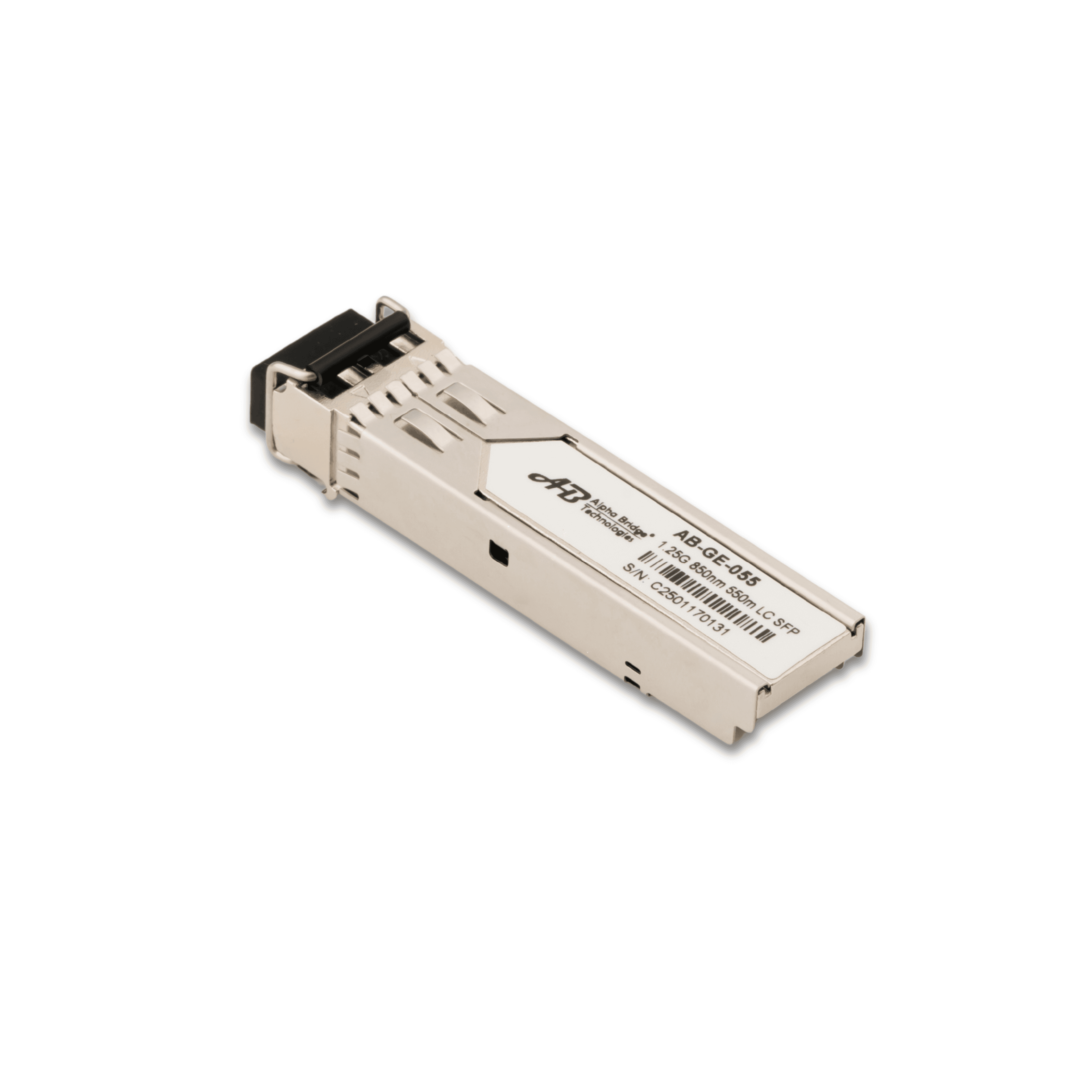
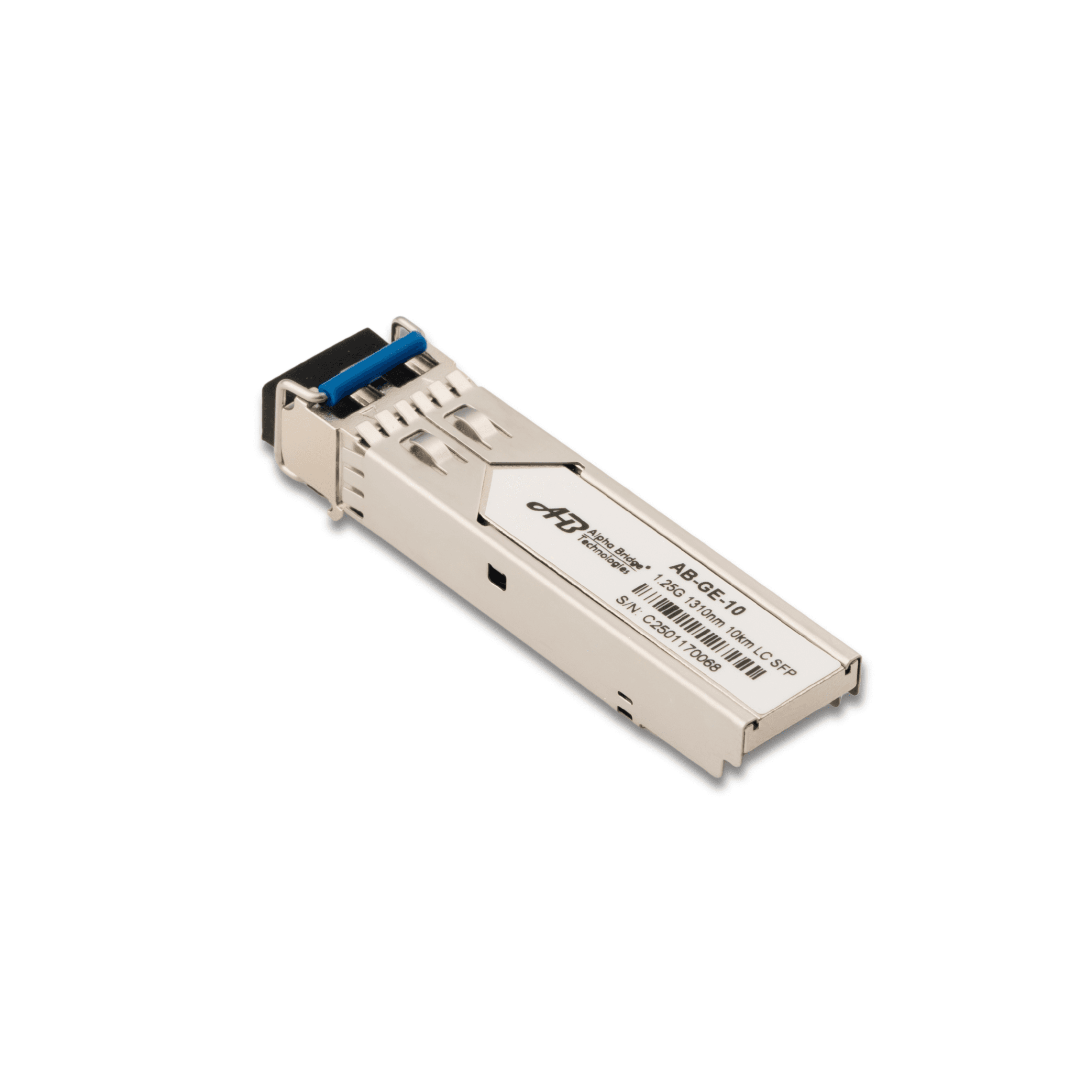
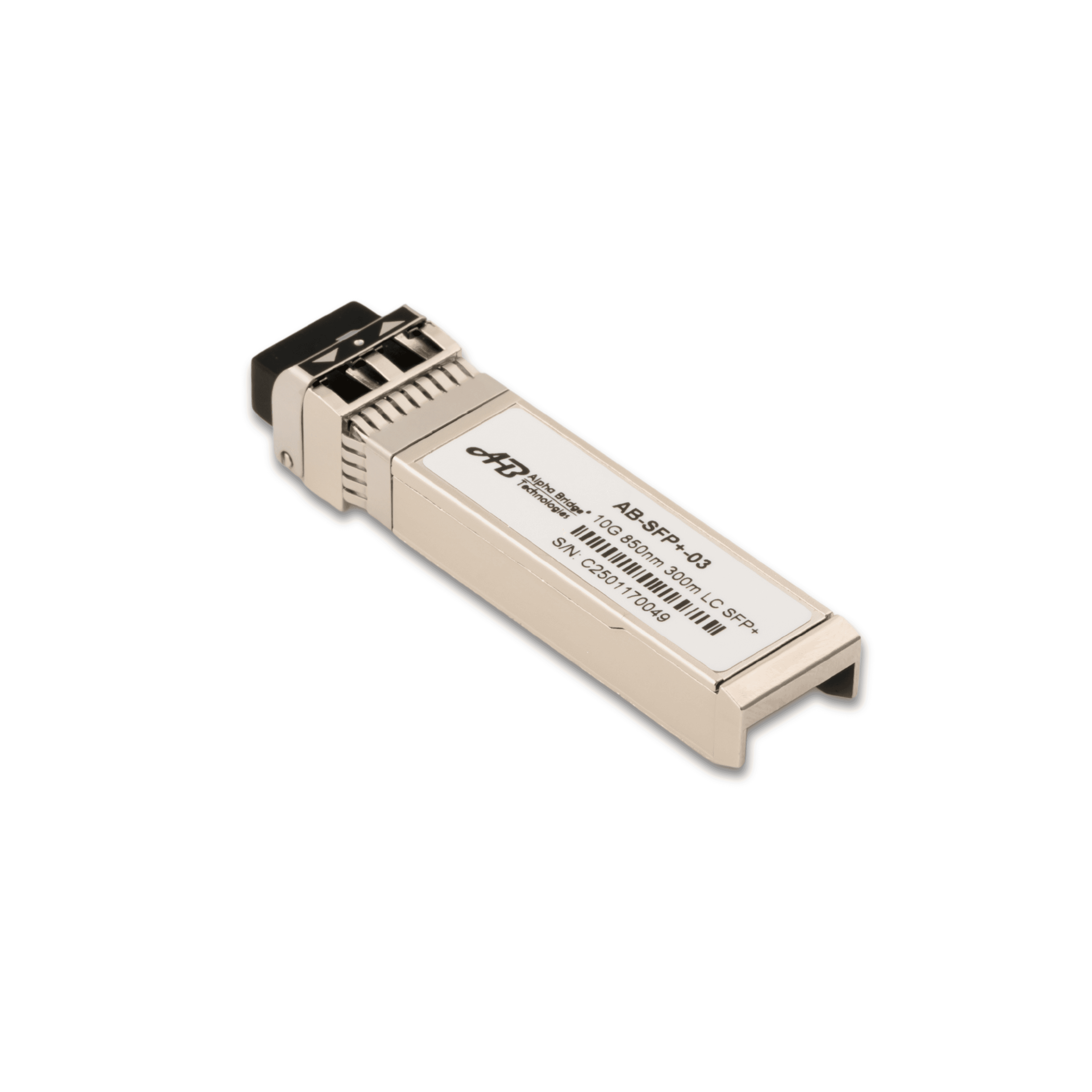
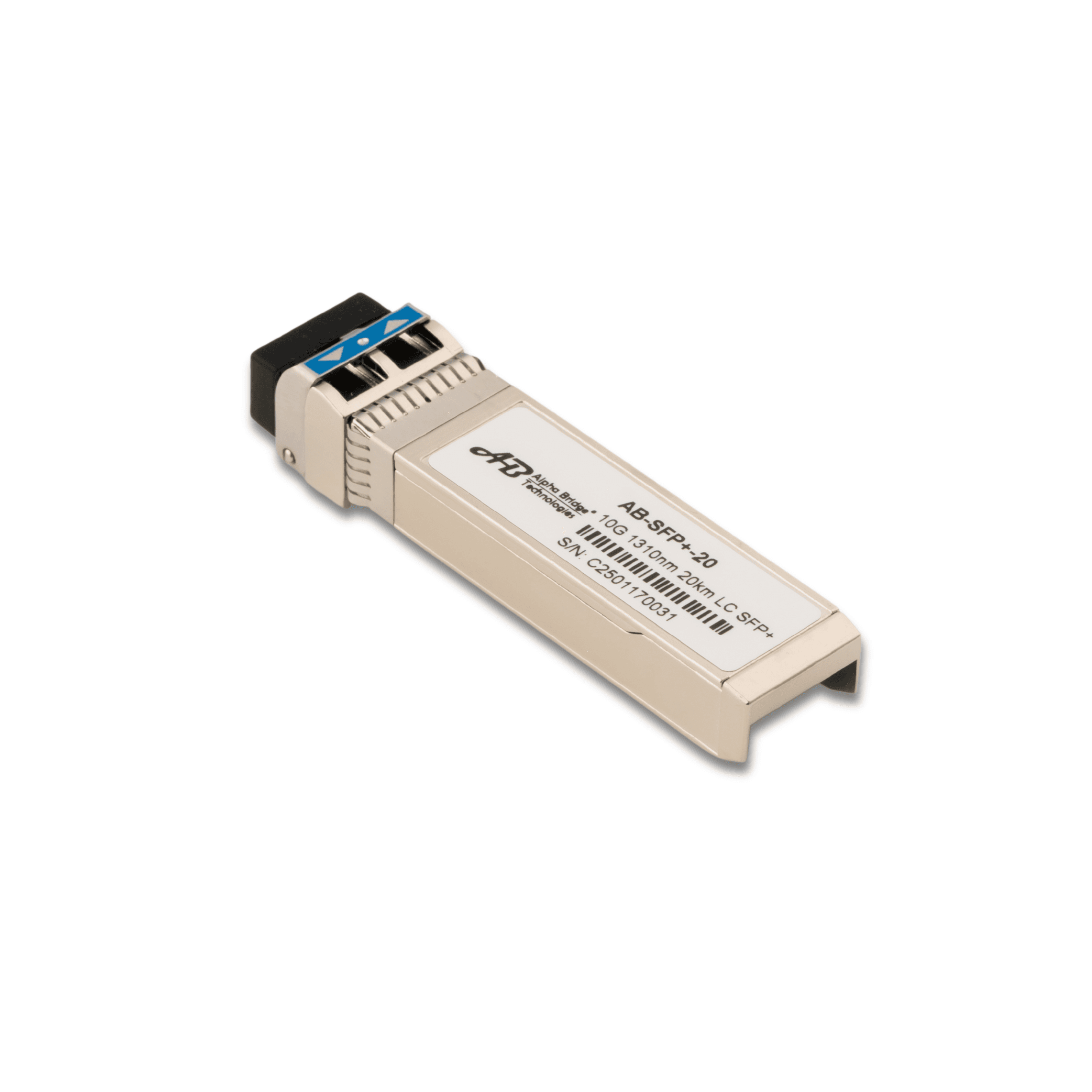
Trusted supply of Energy Meters , Solar Net Meters and High-performance SFP modules enabling EPCs, Installers, and Enterprises to scale clean energy and connectivity.
Discover why businesses rely on STRINEX for their most critical infrastructure needs

CE Energy Meters , Net Meters and CE/RoHS-compliant SFPs.

Fast dispatch from India and Dubai (UAE) Fullfilment Centers.

Bulk orders, partner pricing, and technical documentation for EPCs and enterprises.
Discover our high-quality products designed for reliability and performance
STRINEX delivers integrated solutions in energy and connectivity helping EPCs, Enterprises, and Distributors build efficient, reliable, and sustainable systems.
From Smart Metering and Digital Net Metering to Advanced Networking Solutions we enables a smarter, more connected infrastructure for the modern world.
Complete suite of tools to streamline your B2B operations.
We design and supply energy-efficient equipment, transforming power consumption for industries and households. Our solutions maximize energy use, minimize waste, and reduce costs while promoting sustainability.
We lead in smart grid technology, optimizing energy distribution with real-time monitoring, load balancing, and renewable integration. Our advanced metering options support innovation and efficiency in the energy sector.
STRINEX provides comprehensive Project Management and Data Services in the energy and technology sectors. Our team delivers end-to-end solutions, specializing in data analysis, visualization, and management to optimize resources, enhance decision-making, and drive excellence.

Join our network of EPCs, Distributors, and Enterprises to access priority supply, exclusive pricing, and dedicated support ensuring your projects succeed with confidence.
Discover the latest updates, insights, and stories from STRINEX.

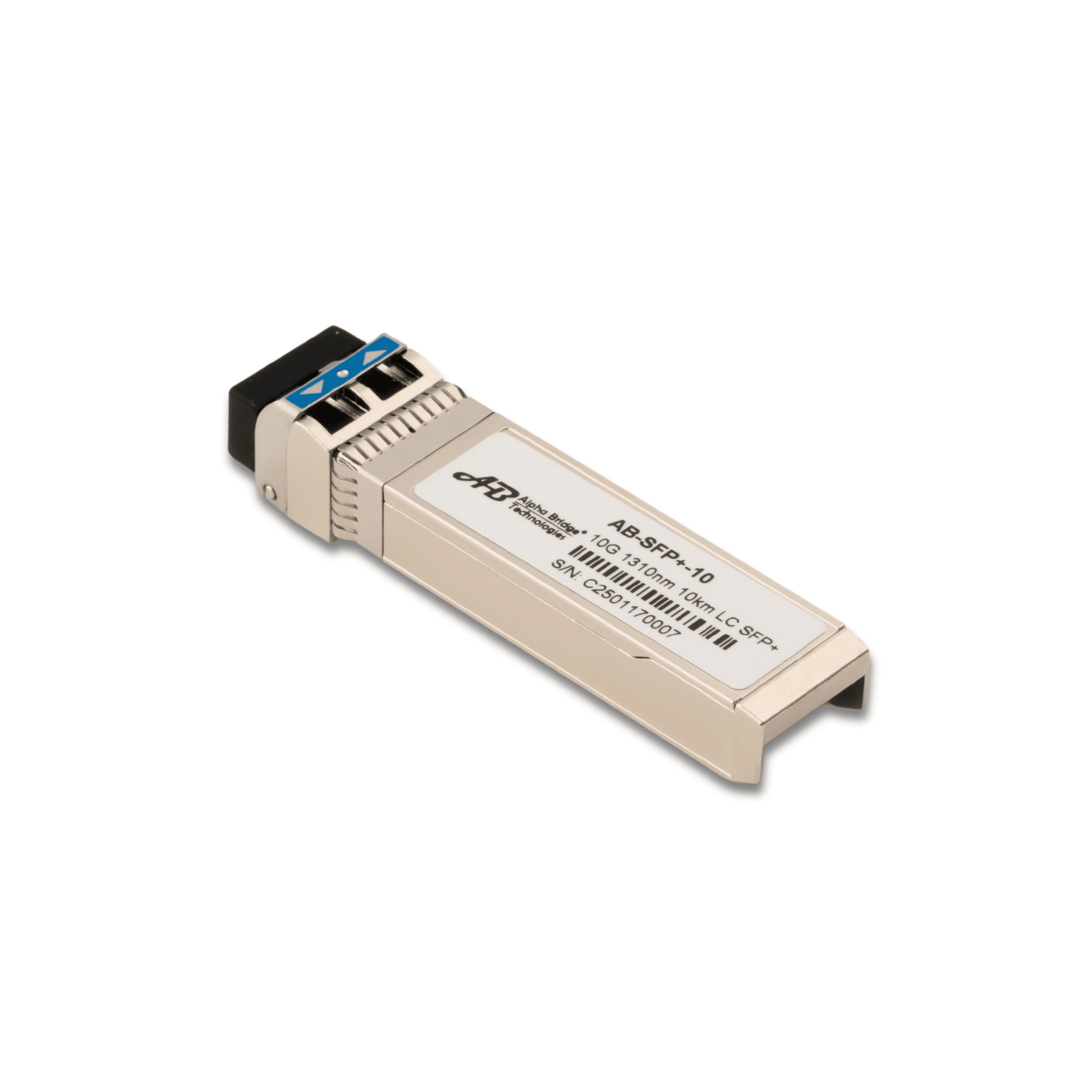
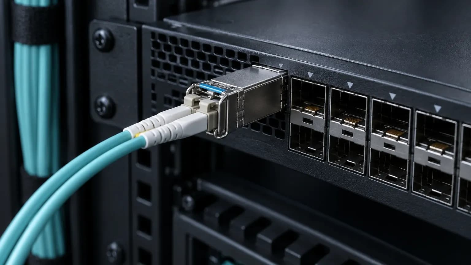
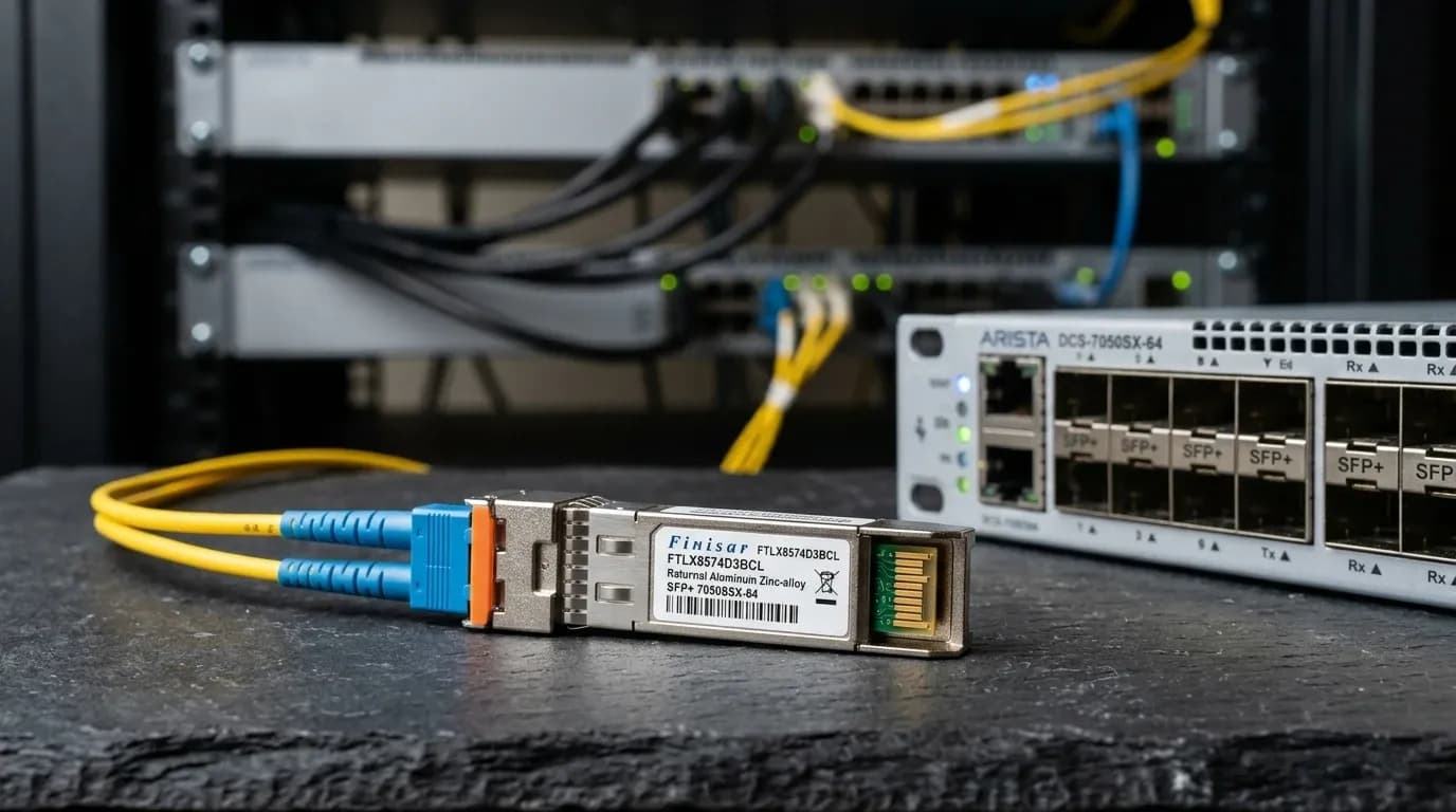
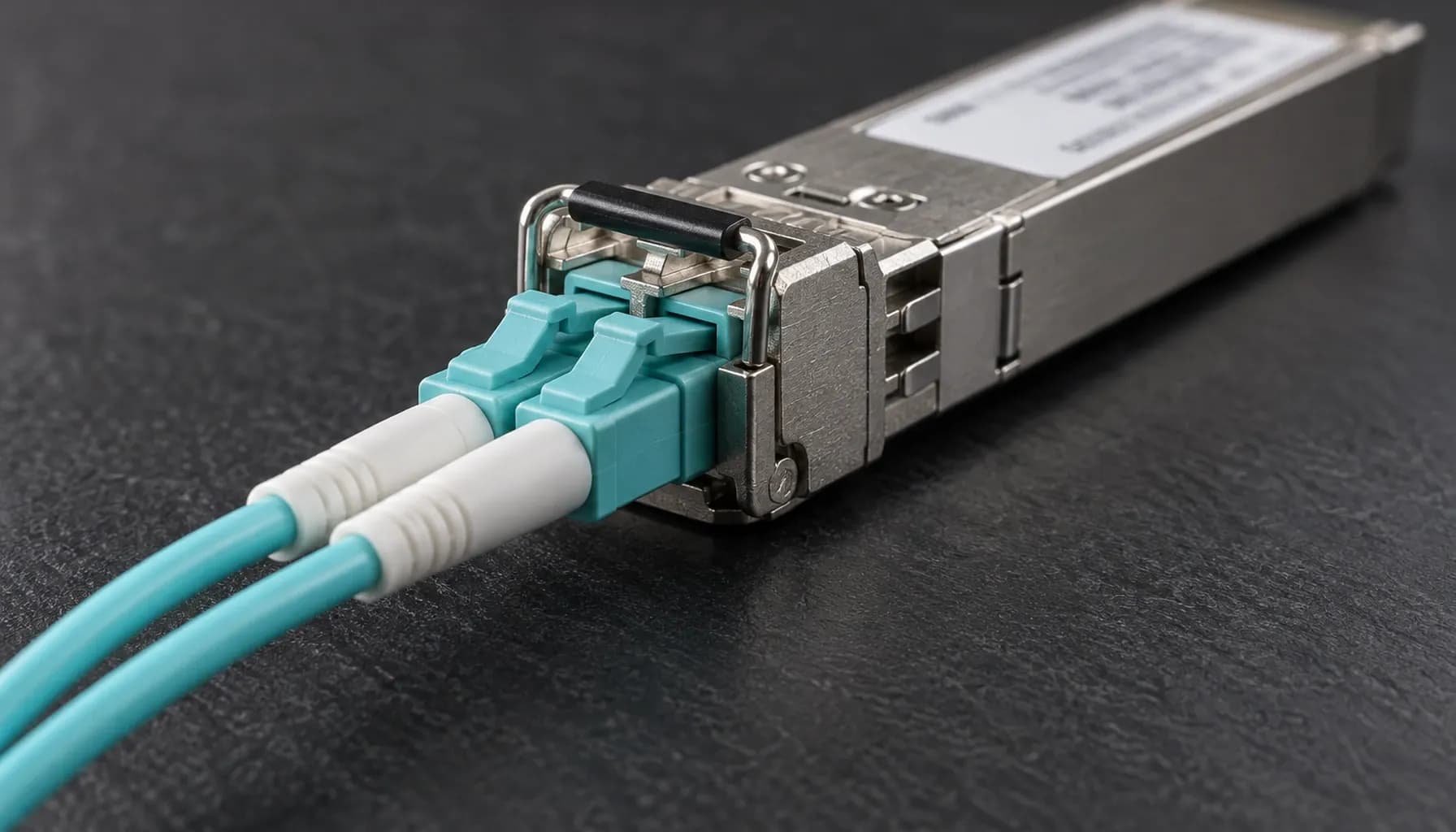
An SFP+ module can slide into the right cage, light its laser and still fail the deployment. The host may reject its EEPROM coding, or the fiber channel may be wrong for the wavelength. In UAE change windows, that distinction becomes painful fast. For teams evaluating SFP+ transceiver compatibility across Cisco, Juniper and Arista, start with the exact switch, software release, port and fiber path. A vendor name on the module label is not a compatibility result. SFP+ compatibility is more than fitting the port A sound 10GbE link needs a 10G-capable host port, the SFF-8431 SFP+ interface, a compatible optical channel, and EEPROM coding the host accepts. A live link does not establish OEM support eligibility. Check port speed first. A 1G SFP port is not automatically a 10G SFP+ port. Then match the circuit: standard, wavelength, fiber type, connectors and Tx/Rx polarity. Record the module part number, host model, software release, DOM readings and interface state before diagnosing loss or policy. Start with the 10GBASE-SR physical link 10GBASE-SR is a short-reach multimode design. The Alpha Bridge ASFP-10G-SR is specified for 10Gbps, 850nm, LC duplex, OM3/OM4 multimode fiber and a reach of up to 300m. Treat those as a single design envelope. Mixing an SR optic with OS2 single-mode fiber is simply the wrong circuit. The Alpha Bridge ASFP-10G-SR 10G SFP+ optical transceiver needs matching SR optics at the far end, LC-duplex OM3 or OM4 fiber, and a span inside its stated limit. Measure the channel rather than trusting a cable label. Available optical budget is P_budget = P_Tx_min - S_Rx_sens. Compare it with total channel loss using the selected module's datasheet values, then keep at least 3dB margin. That margin covers connector contamination, aging and the small surprises that show up after a rack is closed. | Parameter | ASFP-10G-SR requirement | Failure symptom | |---|---|---| | Host port | 10G SFP+ capable | Module unrecognized or no link | | Optics | Matching 10GBASE-SR at 850nm | No optical link | | Fiber | LC duplex OM3/OM4 multimode | Unstable link or no link | | Reach | Within the 300m product rating | Insufficient margin | | DOM | Within module thresholds | Alarms or flaps | Key takeaway: An SR circuit is a channel design, not two arbitrary modules joined by a patch lead. Cisco, Juniper and Arista: what compatibility means SFF-8431 defines the SFP+ form factor. SFF-8472 defines DOM/DDM diagnostics through the serial interface, including address 0xA2. Neither standard forces every host to accept every vendor-coded optic. Each vendor decides acceptance and support by platform, optic and software release. | Vendor | Authoritative check | Support caveat | Safe next step | |---|---|---|---| | Cisco | Exact platform and release documentation | Acceptance and support are platform-specific | Validate model/release and capture DOM/link results | | Juniper | Hardware Compatibility Tool | JTAC support is limited for non-qualified optics | Match device and optic in HCT; test the port | | Arista | Transceiver and Cable Guide | Platform and EOS release need verification | Confirm guide applicability; test link and DOM | | Parameter | Strinex Alpha Bridge | FS.com equivalent | Cisco OEM | Generic or refurbished | |---|---|---|---|---| | Data rate | 10Gbps SFP+ | Confirm selected SKU | Confirm selected SKU | Verify exact SKU | | Wavelength / fiber | 850nm, LC duplex OM3/OM4 | Confirm selected SKU | Confirm selected SKU | Verify label and EEPROM | | Maximum reach | Up to 300m | Confirm selected SKU | Confirm selected SKU | Verify datasheet and conditions | | DDM/DOM support | SFF-8472 diagnostics | Confirm selected SKU | Platform/SKU dependent | Validate before deployment | | Switch compatibility | Check host model/release first | Coding and host validation | Qualified supported hosts | Highest validation burden | | UAE delivery time | Confirm Dubai availability | Confirm at order | Confirm at order | Confirm source and lead time | | Warranty | Confirm product-specific terms | Confirm terms | Confirm terms | Confirm provenance and terms | Cisco: validate the platform-specific policy Cisco behavior varies across the portfolio. Cisco documents service unsupported-transceiver in ISR1000 IOS-XE optic-support guidance. That scope matters. Do not carry the command into Catalyst or Nexus because a forum post said it worked elsewhere. Where the documented ISR1000 case applies, the command is an administrative choice, not a qualification guarantee: For Catalyst and Nexus, use documentation for the exact model and release. Review port speed, notices, DOM and error counters. A clean link is not an OEM support ruling. Juniper: use HCT and understand the JTAC boundary Juniper's Hardware Compatibility Tool is the first check for the exact EX or QFX device, interface and optic combination. A third-party module may link and still not qualify for JTAC support. Match the Junos release to the HCT result and keep a qualified rollback optic for support-sensitive paths. Arista: validate against the Transceiver and Cable Guide For Arista, check the Transceiver and Cable Guide for the exact switch platform and EOS release. A claim that an optic works in a 7050SX does not answer whether it fits the target host and release. Test the cable plant after the guide check. Review link state, error counters and DOM after the circuit stabilizes. Use DOM before and after production cutover SFF-8472 diagnostics report temperature, supply voltage, laser bias and Tx/Rx optical power, so engineers can baseline a circuit before cutover. Compare readings with the module's published warning and alarm thresholds. Low receive power can point to dirty ferrules, excess loss, reversed polarity or a damaged patch lead. Record the timestamp, fiber run, host port and part number. Inspect and clean LC ferrules before mating, following IEC 61300-3-35 practice. Cap open ports and keep bend radius above 30mm where cable construction permits. Use a cleaner, optical power meter and visual fault locator before repeated reseating. UAE procurement checklist A deployment-ready request identifies the switch, software release, port, fiber type and length, coding requirement, and whether OEM qualification is mandatory. Use the Alpha Bridge ASFP-10G-SR 10G SFP+ optical transceiver only for its specified 850nm, LC-duplex OM3/OM4, 300m SR design. Confirm Dubai availability, delivery timing and product-specific warranty/RMA terms before booking the change. Fluke Networks CertiFiber Pro certifies multimode channel loss. EXFO FLS-600 provides controlled optical testing. Fluke Networks FI-3000 inspects connector end faces. Frequently asked questions Are third-party SFP+ modules compatible with Cisco switches? They can be, but compatibility remains platform- and release-specific. Confirm the 10G SFP+ port, optic type and exact Cisco documentation. ISR1000 guidance for service unsupported-transceiver does not apply by default to Catalyst or Nexus. Do Juniper switches accept third-party SFP modules? They may accept them electrically and optically, but acceptance does not equal JTAC qualification. Check HCT for the precise device and optic, then test the target port. Does Arista support non-Arista-branded transceivers? It depends on the switch, optic and EOS release. Check the applicable Transceiver and Cable Guide entry, then validate link stability and DOM in a controlled test rather than relying on a generic claim. What is SFP+ DOM? SFP+ DOM is the module diagnostic interface. It reports temperature, voltage, laser bias and Tx/Rx optical power. Compare those values with the module's own thresholds before and after the change. Can I use a 10G SFP+ module on OM3 fiber? Yes, when the 10GBASE-SR module is designed for multimode fiber and the entire channel matches. ASFP-10G-SR requires LC-duplex OM3/OM4 fiber and a span within 300m. Match the far-end optic and verify polarity. Takeaways for network architects Match port speed, optic standard, wavelength, fiber class, connector and polarity before assessing coding. MSA compliance enables interoperability but does not guarantee host acceptance or OEM support eligibility. Validate Cisco, Juniper and Arista by exact platform and release; do not transfer bypass guidance between families. Confirm the exact host before buying Reliable SFP+ transceiver compatibility across Cisco, Juniper and Arista comes from channel design and host-specific validation, not a universal promise. Send Strinex the switch, OS/EOS/Junos release, port and fiber run for a pre-purchase check. Review the Alpha Bridge ASFP-10G-SR 10G SFP+ optical transceiver , then confirm Dubai stock and warranty terms. Related Engineering Guide: 10GBASE-SR vs 10GBASE-LR: Choosing the Right SFP+ for OM3 vs OS2 in UAE (2026)

A 25G link does not become reliable because someone selected the strongest-looking FEC option. It becomes reliable when both endpoints, their software releases, and the installed SFP28 optic or cable agree on a supported mode. Miss that detail and you get the familiar failure: the port is enabled, the module is accepted, and the link still will not stay up. For data-centre and industrial-network teams, FEC is an endpoint-agreement problem with a physical-media dependency. Record the switch or NIC model, firmware, port speed, exact media part number, and span before changing anything. In Dubai Internet City data centres, where a failed uplink can strand a line card or storage path, that record is cheaper than a long vendor escalation. Base-R vs RS-FEC: what the two modes mean Base-R and RS-FEC are not interchangeable quality settings. They are different coding options that the two 25G interfaces and the selected medium must both support. Pick the documented common mode, then watch the link and its counters over an agreed period. Do not assume that a default on one platform carries across vendors. IEEE 802.3 Clause 91 defines RS-FEC. BASE-R FEC belongs to the IEEE 802.3 physical-coding framework. RS-FEC has greater correction capability, but support, operating overhead, and interoperability depend on the platform. There is no honest universal latency number to put in a design document. | Decision point | Base-R FEC | RS-FEC | Evidence required | |---|---|---|---| | Role | Supported 25G coding option on relevant hosts and media | Clause 91 Reed-Solomon FEC option | Switch/NIC release documentation | | Selection rule | Use it only when both ends and media list it | Use it only when both ends and media list it | Exact port and media part numbers | | Interoperability | Do not infer it from form factor | Do not infer it from form factor | Supported-mode output and release notes | | Change risk | A mismatch can hold the link down or make it unstable | A mismatch can hold the link down or make it unstable | Maintenance-window rollback plan | Key takeaway: The SFP28 label does not prove that either Base-R or RS-FEC will work. The endpoints and installed medium provide that proof. Why the exact medium changes the FEC decision A few metres of copper can change the applicable rule. So can the module family. Cisco's 25G documentation provides useful examples, but only for listed Cisco SKUs and platforms: certain 1-2 m DAC cases use no FEC, some 2.5-3 m cases use BASE-R FEC, and some 4-5 m cases use RS-FEC. Its documentation also calls for RS-FEC on specified 25G SR, LR, and CSR applications. Treat those as vendor-specific engineering constraints, not a template for every passive DAC, AOC, or SFP28 optic. Procurement records need the supplier part number, not a description such as "25G DAC" or "25G SR." For optical links, check the fibre class, connector condition, patching, and module documentation alongside FEC. The guidance in SFP+ transceiver compatibility on Cisco, Juniper and Arista is relevant here: host qualification and EEPROM or DOM visibility do not prove that a particular FEC mode is valid. Build a two-endpoint FEC compatibility record A two-endpoint record turns an intermittent incident into a decision another engineer can review. Capture it before a change and keep it with the maintenance record. | Field | Endpoint A | Endpoint B | |---|---|---| | Switch/NIC model and port | | | | OS, driver, and firmware release | | | | Port mode and negotiated speed | | | | Exact optic or cable part number | | | | Medium, fibre type, and measured length | | | | Current and documented supported FEC | | | | Link, corrected, and uncorrectable counters | | | Confirm 25G operation before interpreting FEC. MSA form-factor compliance says that the hardware fits; it does not guarantee a shared FEC implementation. The host vendor's release documentation decides the question. Safe sequence for a 25G FEC mismatch Do not begin by copying a generic command from a forum. Syntax, privileges, operational semantics, and defaults vary between switch operating systems and NIC drivers. Preserve the current state, compare both ends, and change one controlled variable at a time. Capture interface state, negotiated speed, configured and operational FEC, module or cable identity, and error counters at both ends. Verify the physical medium, length, and exact data sheet. Compare each host's release-specific supported modes. Use a maintenance window. Apply one documented common mode on both endpoints and retain the prior state for rollback. Check link persistence, speed, and counters during the agreed observation period. Revert and escalate with the evidence record if errors or instability continue. A working peer in another rack proves very little. Its NIC revision, cable length, or software level may differ. The 10GBASE-SR vs 10GBASE-LR selection guide makes the same point for fibre selection: match the media to the documented application instead of relying on the connector type. FEC counters do not replace physical-layer checks Corrected FEC events mean the receiver recovered impaired symbols. Uncorrectable events mean correction was insufficient. Neither counter identifies the fault by itself. Inspect both end faces using IEC 61300-3-35 cleaning and inspection practice, confirm fibre polarity, verify cable or optic type, and inspect routes for tight bends, crush damage, or thermal exposure. This matters in Abu Dhabi industrial SCADA networks, where a disturbed cable route may look acceptable until temperature or vibration changes. Inspect first. Use a one-click cleaner only when inspection calls for it, then inspect again before reconnecting. Use an optical power meter or visual fault locator where the installed media and acceptance plan warrant them. Do not invent a dB, BER, or corrected-counter threshold when the module, link, and platform acceptance criteria have not defined one. DOM or DMI telemetry can support the diagnosis when the module and host expose it. Diagnostic tools worth using Good diagnosis combines endpoint evidence with physical-layer inspection. Fluke Networks CertiFiber Pro supports fibre-certification workflows. EXFO MaxTester 720C fits OTDR-based fibre investigation. Configure either tool for the installed media and the project's acceptance plan. Fluke Networks FI-3000 provides fibre-endface inspection and automated pass/fail assessment against supported criteria. Fluke Networks CertiFiber Pro measures optical loss for documented fibre-cabling certification workflows. EXFO MaxTester 720C locates and characterises fibre events where an OTDR workflow is appropriate. Frequently asked questions Must both 25G endpoints use the same FEC mode? Yes. Both endpoints must configure or negotiate a mutually documented mode for the installed port, software, and medium. RS-FEC on one side does not prove that the far end supports it. Compare operational state, not intended configuration. Is RS-FEC always better than Base-R FEC? No. RS-FEC is not a universal upgrade. Use the mode that both endpoint documents and the exact cable or optic specify. A stronger-looking setting can still create a mismatch. Does every 25G SFP28 SR optic require RS-FEC? No. Requirements depend on the product and host. Cisco's optical requirements are useful for the Cisco applications they list, but they do not apply automatically to every SFP28 SR module. Obtain the module data sheet and host compatibility evidence. Can engineers ignore corrected FEC errors? No. Corrected errors deserve trend review and a physical-layer inspection. They can point to a developing connector, cable, optic, route, or environmental problem while traffic still passes. Escalate against the site's documented acceptance criteria. Should an engineer use a generic CLI FEC command from the internet? No. Commands and semantics differ by switch OS, NIC driver, and release. Use the vendor documentation for the actual endpoint, capture the present configuration, and preserve rollback evidence before a controlled change. Takeaways for network architects Treat FEC selection as a documented agreement between both endpoints and the exact installed medium. Treat Cisco DAC and optical examples as SKU-specific references, never as defaults for every 25G SFP28 link. Record software revisions, part numbers, operational FEC, and counters before changing configuration. Pair FEC-counter analysis with endface cleaning, polarity, route, and environment checks. Conclusion and local UAE procurement The reliable approach to 25G SFP28 FEC configuration is simple in principle and demanding in practice: find the documented common mode, apply it symmetrically during a controlled window, then verify stability and the physical media. Before buying replacement optics or cables, provide Strinex with the host models, software releases, port speeds, exact part numbers, media and length, plus current FEC evidence. Confirm Dubai availability, dispatch timing, and support coverage directly with the team. For host-qualification planning, review SFP+ transceiver compatibility on Cisco, Juniper and Arista .

Introduction A 10G uplink rarely fails because somebody forgot the headline bandwidth figure. It fails because east-west traffic has grown past the oversubscription plan, or because a high-density server row now feeds storage, AI training, and backup windows through the same pair of links. In Dubai Internet City data centres, that pressure often arrives during a refresh cycle when nobody wants to re-cable a live hall. The sensible path is 25G at the server edge and 100G in aggregation, planned as one optical system rather than three disconnected purchase orders. The same discipline matters outside the white space. Abu Dhabi industrial SCADA networks may not need a 100G core, but their control-room backhaul still needs predictable latency, resilient optics, and a failure domain that an operator can diagnose under pressure. Treat the migration as an architecture decision: map traffic, cable plant, port capabilities, forward error correction (FEC), and operating conditions before ordering modules. Technical operating principles and specification checks 25G uses one 25.78125 GBd electrical lane; 100G QSFP28 commonly aggregates four 25G lanes. That makes 25G the clean replacement for one 10G server connection and gives a 4 x 25G breakout a practical path into a 100G leaf or spine port. It does not make SFP+ and SFP28 electrically interchangeable in every host. Confirm each line card, NIC, and network operating system before treating a cage as backward compatible. Optical selection starts with loss, not a distance label. Use the minimum transmit power and the receiver sensitivity to calculate available margin: $P_{\text{budget}} = P_{\text{Tx\_min}} - S_{\text{Rx\_sens}}$ Subtract fibre attenuation, connector and splice loss, then keep a realistic maintenance reserve. A link with 6 dB of available budget, 3.2 dB of calculated channel loss, and no reserve is not an approved design. It is a future fault ticket. For short intra-row runs, 850 nm SR optics on verified OM4 are economical. For campus-scale links, OS2 single-mode fibre and LR optics offer the cleaner migration path; the OS2 versus OM3/OM4 fibre design guide explains the cable-plant trade-off. Use Strinex 10G/25G optical transceivers only after matching wavelength, connector type, reach, host qualification, and DDM support to the approved channel. The module price is small beside a late-night outage caused by an unqualified optic. Comparison matrix | Parameter | Strinex Alpha Bridge | FS.com Equivalent | Cisco OEM | Generic / Refurbished | | --- | --- | --- | --- | --- | | 10G/25G migration fit | Confirm coded SFP+/SFP28 SKU and host support | Match exact speed and coding | Use the approved optic matrix | Verify label, EEPROM, and data sheet | | 100G aggregation | Select qualified QSFP28 or breakout assembly | Confirm FEC and breakout support | Confirm platform release support | Treat interoperability as unproven | | Optical budget evidence | Require Tx/Rx limits and DOM values | Require the same published limits | Use Cisco documentation | Measurements may be incomplete | | UAE support path | Local stock and warranty route | Confirm delivery and RMA path | OEM support contract required | Provenance and warranty vary | | Deployment risk | Low after host and channel validation | Low after host and channel validation | Low on supported platforms | Highest; test before production | Do not turn this table into a brand argument. A coded compatible optic can be a sound choice when its specifications, host behaviour, and support route are documented. A cheap module with no traceable test data is a false economy on a spine link. Interoperability and host validation Cisco Nexus, Juniper QFX, Arista 7050X, and MikroTik platforms can carry the same Ethernet services, but their acceptance of optics, FEC defaults, and breakout syntax differ. Build a small acceptance matrix with the exact host model, software release, port speed, optic part number, fibre type, FEC mode, and measured Rx power at both ends. Test it before the maintenance window. At 25G and 100G, negotiate neither speed nor FEC by assumption. A link can show carrier while accumulating corrected symbols, then fall over when load increases. Lock both ends to the approved mode and inspect counters after a sustained traffic test. Use the 25G SFP28 FEC configuration guide when the port documentation leaves a choice between Base-R and RS-FEC. For remote or industrial cabinets, validate temperature, power feed, grounding, and enclosure heat separately from the data-centre design. The hardened DIN-rail switch guide is relevant when the migration crosses into control networks. High speed does not excuse a poor environmental design. Field deployment and maintenance Protect the channel during installation. Keep the cable bend radius above $30\text{ mm}$ unless the cable manufacturer specifies a larger value. Do not pull a patch lead tight around a tray corner, and do not close a cabinet door against a fibre loop. A stressed bend can pass commissioning and introduce loss after heat cycling. Adopt IEC 61300-3-35 ferrule inspection and cleaning as a release gate. Inspect the end face, clean with the approved dry or wet-dry process, inspect again, and cap every disconnected connector. Never clean a connector merely because it looks dirty under room light. Record baseline Tx/Rx power after acceptance, then compare DDM readings against that baseline rather than a generic alarm threshold. Recommended diagnostic utilities and testing tools Fluke Networks FI-7000 FiberInspector Pro checks ferrule end faces for contamination, pits, and scratches before a module sees the connector. EXFO MaxTester 720C OTDR locates splices, connectors, and macro-bends in a suspect fibre run. VIAVI SmartOTDR combines fibre characterisation with field-friendly trace capture for handover records. Frequently asked questions Should a UAE data centre move from 10G directly to 100G? Use 25G at the server edge when the NIC and switch support it, then aggregate four 25G lanes into 100G where traffic warrants it. This preserves port density and keeps the migration incremental. A direct 100G server connection makes sense for specialised high-throughput workloads, not as a default refresh choice. Can an SFP+ optic run in an SFP28 port? Many SFP28 host ports can operate at 10G with an SFP+ optic, but the host documentation decides the answer. Confirm supported speed, coding, and software release on that specific port. Test the actual module pair, rather than relying on physical cage compatibility. Which FEC mode should a 25G link use? Use the mode specified by both endpoints and the optical or DAC channel requirements. RS-FEC adds stronger correction and can be necessary on marginal or longer channels, while Base-R may suit supported short links. A mismatch is a configuration fault, even if the link initially appears healthy. How much optical margin should the design retain? Calculate measured and specified losses first, then reserve margin for connector ageing, contamination, and future patching. The exact reserve belongs to the project standard and risk profile. Do not approve a circuit that only works at its published receive threshold. Are refurbished optics suitable for a 100G spine? They can pass traffic tests, but provenance, firmware state, thermal history, and warranty can be difficult to establish. Use traceable, supported parts for production spines and reserve unknown stock for lab work. The cost of one intermittent spine fault exceeds the saving quickly. UAE selection checklist Map the 10G, 25G, and 100G traffic tiers before selecting modules; bandwidth figures alone do not define the architecture. Approve fibre type, wavelength, connector count, and the calculated optical budget for every channel. Validate the exact Cisco, Juniper, Arista, or MikroTik host and software release with the selected optic and FEC mode. Keep bends above $30\text{ mm}$, inspect ferrules to IEC 61300-3-35, and retain baseline DDM readings at handover. Buy a support path and documented warranty, not just a part number. Conclusion and local UAE procurement A reliable 10G-to-25G-to-100G migration uses 25G to increase server-edge density and 100G to consolidate aggregation, while keeping FEC, optics, and fibre loss under engineering control. The design survives production when the acceptance matrix and baseline measurements are complete before the cutover. For Dubai projects with a short maintenance window, local stock and same-day dispatch reduce the risk of waiting on a replacement module. Review the live Strinex 10G/25G optical transceiver range , then confirm the exact compatible SKU and channel specification with the engineering team before release.

STRINEX continues to expand its presence across India and the UAE as part of its long-term vision to build intelligent, scalable, and sustainable infrastructure solutions for modern businesses. Operating across the clean energy and enterprise connectivity sectors, the company is focused on supporting EPC partners, industrial businesses, commercial infrastructure projects, and enterprise technology deployments through a growing ecosystem of energy and networking solutions. The STRINEX portfolio currently includes UPNEDA-approved digital net metering solutions, enterprise-grade networking products, and infrastructure technologies designed to support the evolving requirements of smart energy and connected business environments. Over the past year, STRINEX has expanded operational capabilities across India and the UAE, strengthened regional fulfillment infrastructure, and continued development of its B2B technology ecosystem to support faster deployment, partner engagement, and customer experience. The company is actively working with EPC companies, system integrators, infrastructure partners, and enterprise customers across multiple sectors, including renewable energy, commercial power infrastructure, fiber connectivity, and intelligent networking environments. “STRINEX is being built around the idea of connected infrastructure — where energy, technology, and operational intelligence work together to support long-term progress,” said Amit Singh, Director at STRINEX. “As industries continue moving toward smarter and more sustainable systems, our focus remains on building reliable infrastructure ecosystems that are scalable, future-ready, and capable of supporting evolving business requirements across regional markets.” The company’s current growth strategy includes expansion across: Smart net metering infrastructure Solar and energy ecosystem support Enterprise networking technologies Fiber connectivity infrastructure Intelligent power and communication systems AI-enabled operational infrastructure STRINEX is also continuing development of its digital commerce and infrastructure platform to simplify B2B procurement, operational workflows, and partner collaboration across India and GCC markets. With increasing demand for sustainable infrastructure, intelligent connectivity, and energy modernization across the region, STRINEX aims to position itself as a long-term technology and infrastructure partner for businesses seeking dependable and scalable solutions. The company’s roadmap includes continued expansion of energy infrastructure capabilities, stronger regional partnerships, advanced digital operations, and broader integration of intelligent technologies across its ecosystem. About STRINEX STRINEX is a clean technology and intelligent infrastructure company focused on smart energy solutions, enterprise networking technologies, and future-ready business infrastructure. Operating across India and the UAE, STRINEX works with EPC companies, businesses, and infrastructure partners to deliver scalable, reliable, and innovation-driven solutions that support sustainable growth and connected industrial ecosystems.

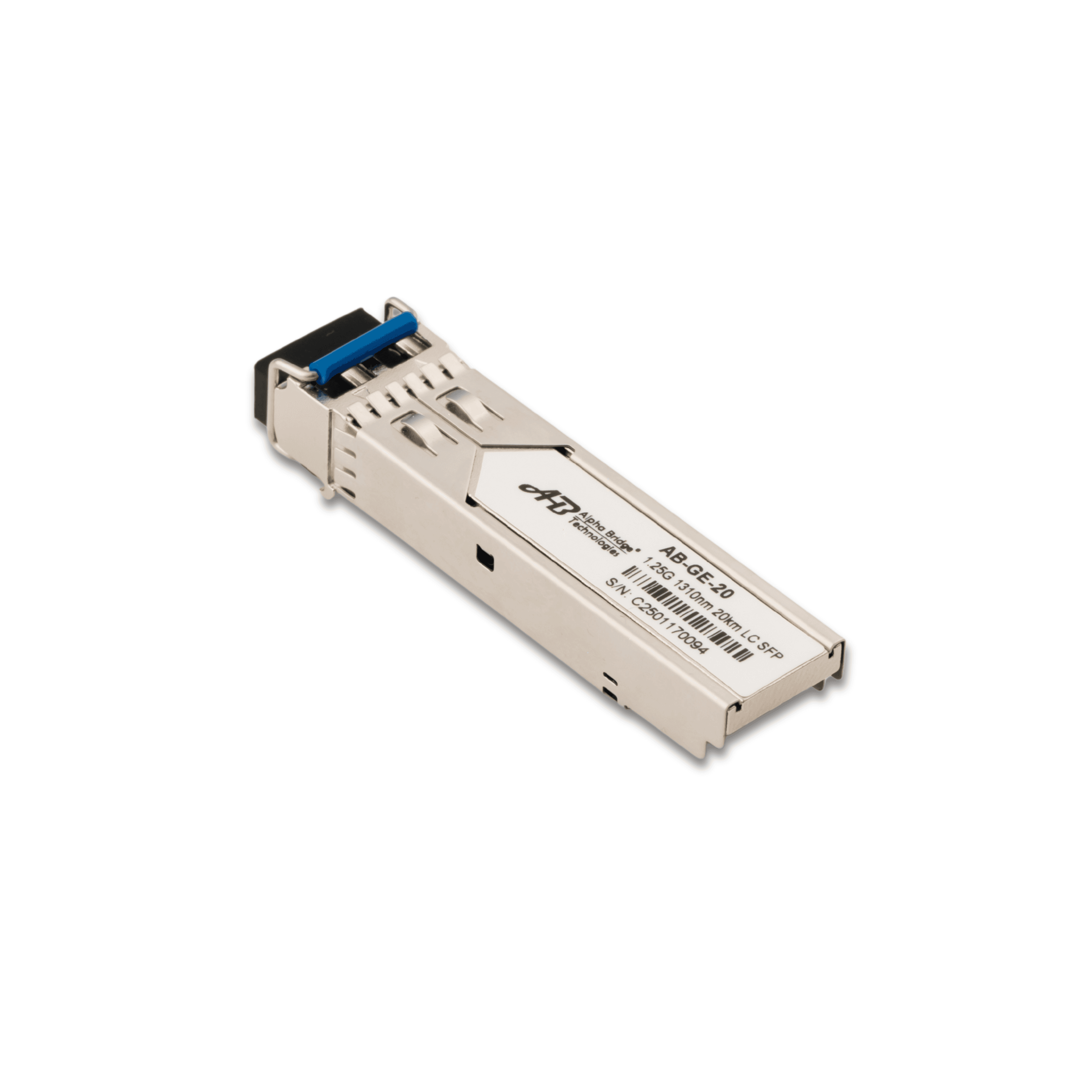
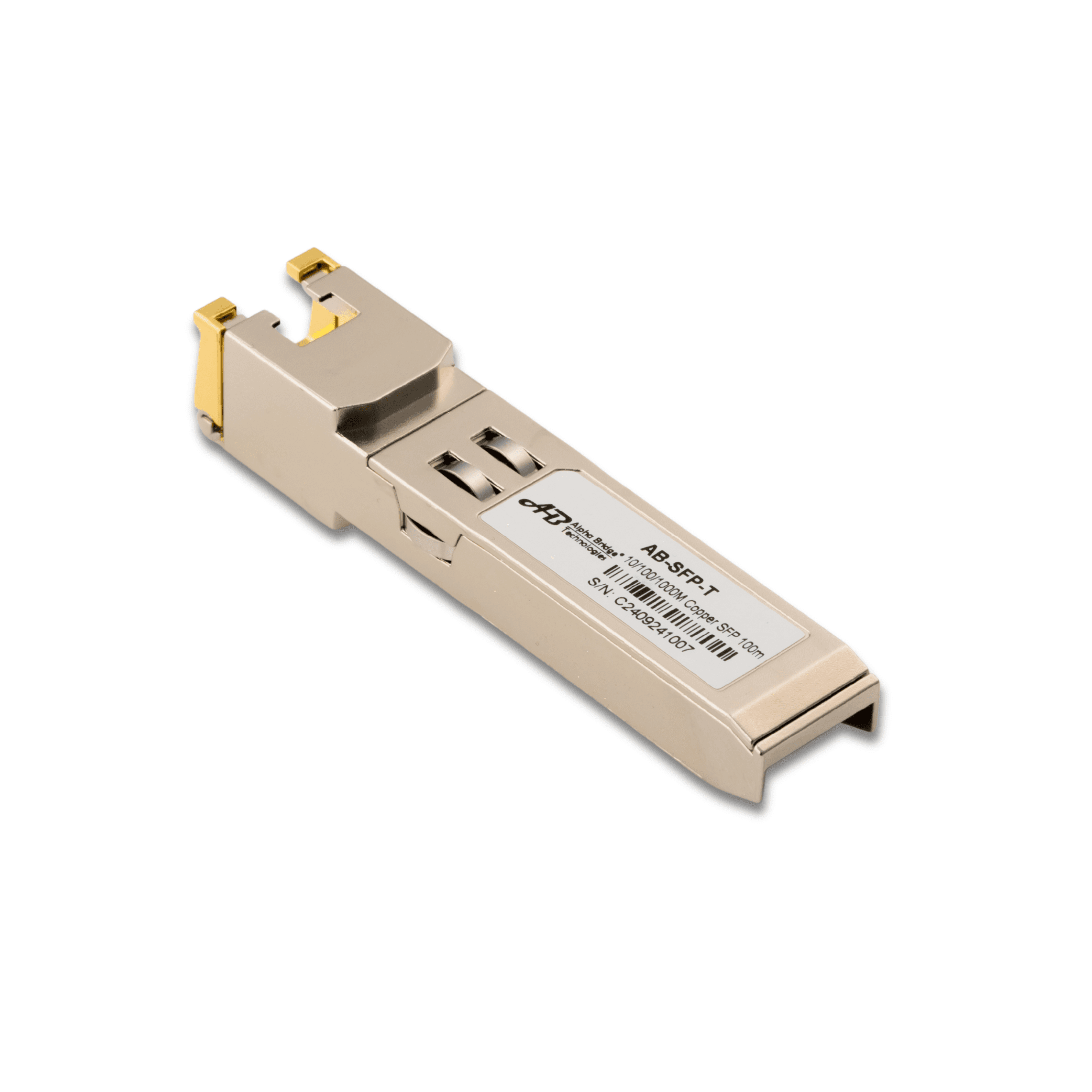
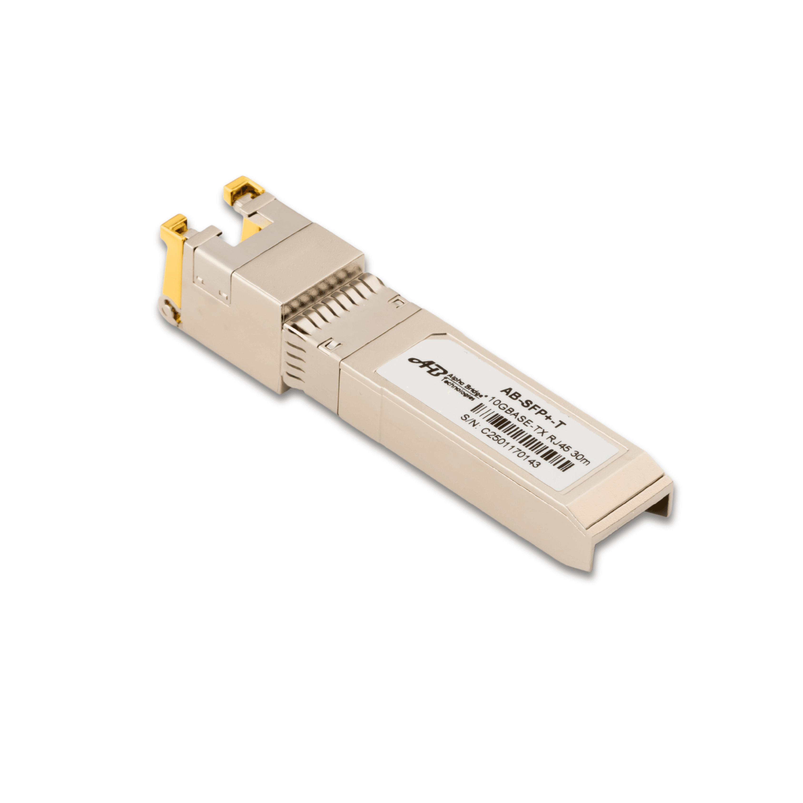
Empowering High-Speed Digital Infrastructure for the Future As businesses, telecom operators, data centers, and enterprises continue to embrace digital transformation, the demand for reliable, high-performance network infrastructure has never been greater. STRINEX is proud to announce the expansion of its Enterprise Connectivity portfolio with a comprehensive range of advanced Fiber Optic and Networking Solutions designed to support modern communication networks. Built for performance, reliability, and scalability, STRINEX networking solutions are engineered to meet the growing requirements of enterprise IT environments, Internet Service Providers (ISPs), telecom infrastructure, industrial automation, surveillance systems, cloud computing, and data center applications. Comprehensive Networking Solutions The STRINEX networking portfolio includes a wide range of enterprise-grade connectivity products, including: 1G and 10G SFP Optical Transceivers SFP+ High-Speed Modules RJ45 Copper SFP Modules Single-Mode & Multi-Mode Fiber Solutions DAC (Direct Attach Copper) Cables AOC (Active Optical Cable) Solutions GPON & Enterprise Fiber Connectivity Products Passive Networking Accessories Each product is designed to deliver high-speed, low-latency, and reliable network performance while ensuring compatibility with leading networking platforms and enterprise environments. Designed for Modern Industries STRINEX connectivity solutions are suitable for a wide range of industries and applications, including: Enterprise IT Infrastructure Data Centers Internet Service Providers (ISPs) Telecom Networks Government & Public Infrastructure Industrial Automation Smart Buildings Educational Institutions Healthcare Networks Hospitality & Commercial Facilities Surveillance & Security Systems Our products are developed to support mission-critical environments where network stability, uptime, and performance are essential. Why Choose STRINEX? At STRINEX, we go beyond supplying networking products. We focus on delivering dependable infrastructure solutions backed by technical expertise and responsive customer support. Our commitment includes: Enterprise-grade quality products Reliable and tested connectivity solutions Technical pre-sales and post-sales support Competitive B2B pricing Fast regional fulfillment Bulk supply capability RFQ and project-based procurement support Operations across India and the United Arab Emirates Whether supporting a small enterprise deployment or a large-scale infrastructure project, STRINEX aims to be a trusted technology partner throughout the project lifecycle. Supporting the Future of Digital Connectivity As digital transformation accelerates worldwide, organizations require networking infrastructure that is scalable, efficient, and future-ready. STRINEX continues to expand its portfolio to support next-generation communication technologies while helping customers build resilient, secure, and high-performance networks. Our long-term vision is to provide integrated infrastructure solutions that combine networking, smart energy technologies, and intelligent digital systems to enable a smarter and more connected future. About STRINEX STRINEX is a technology-driven company specializing in smart energy solutions, enterprise networking products, and digital infrastructure technologies. Operating across India and the United Arab Emirates, STRINEX serves EPC companies, system integrators, telecom providers, industrial customers, utilities, and enterprise organizations with reliable products, technical expertise, and comprehensive project support. Powering a Sustainable Tomorrow.
We partner with global leaders Schneider Electric, Lauritz Knudsen, and Alpha Bridge Technologies to deliver reliable supply and smarter infrastructure. Together, we build stronger networks and drive sustainable growth.