
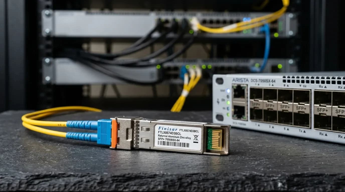
A 25G link does not become reliable because someone selected the strongest-looking FEC option. It becomes reliable when both endpoints, their software releases, and the installed SFP28 optic or cable agree on a supported mode. Miss that detail and you get the familiar failure: the port is enabled, the module is accepted, and the link still will not stay up.
For data-centre and industrial-network teams, FEC is an endpoint-agreement problem with a physical-media dependency. Record the switch or NIC model, firmware, port speed, exact media part number, and span before changing anything. In Dubai Internet City data centres, where a failed uplink can strand a line card or storage path, that record is cheaper than a long vendor escalation.
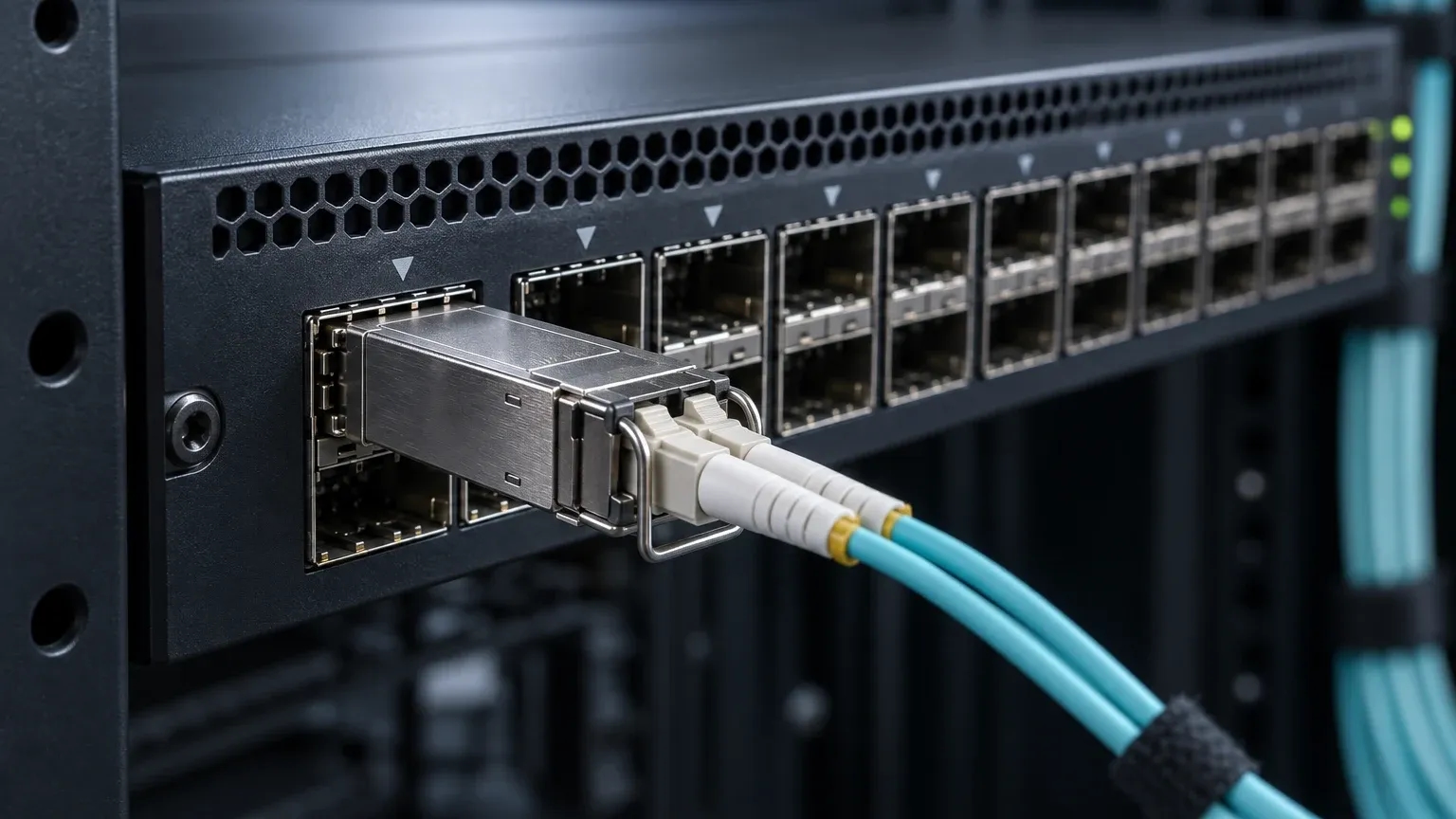
Base-R vs RS-FEC: what the two modes mean
Base-R and RS-FEC are not interchangeable quality settings. They are different coding options that the two 25G interfaces and the selected medium must both support. Pick the documented common mode, then watch the link and its counters over an agreed period. Do not assume that a default on one platform carries across vendors.
IEEE 802.3 Clause 91 defines RS-FEC. BASE-R FEC belongs to the IEEE 802.3 physical-coding framework. RS-FEC has greater correction capability, but support, operating overhead, and interoperability depend on the platform. There is no honest universal latency number to put in a design document.
| Decision point | Base-R FEC | RS-FEC | Evidence required |
|---|---|---|---|
| Role | Supported 25G coding option on relevant hosts and media | Clause 91 Reed-Solomon FEC option | Switch/NIC release documentation |
| Selection rule | Use it only when both ends and media list it | Use it only when both ends and media list it | Exact port and media part numbers |
| Interoperability | Do not infer it from form factor | Do not infer it from form factor | Supported-mode output and release notes |
| Change risk | A mismatch can hold the link down or make it unstable | A mismatch can hold the link down or make it unstable | Maintenance-window rollback plan |
Key takeaway: The SFP28 label does not prove that either Base-R or RS-FEC will work. The endpoints and installed medium provide that proof.
Why the exact medium changes the FEC decision
A few metres of copper can change the applicable rule. So can the module family. Cisco's 25G documentation provides useful examples, but only for listed Cisco SKUs and platforms: certain 1-2 m DAC cases use no FEC, some 2.5-3 m cases use BASE-R FEC, and some 4-5 m cases use RS-FEC. Its documentation also calls for RS-FEC on specified 25G SR, LR, and CSR applications. Treat those as vendor-specific engineering constraints, not a template for every passive DAC, AOC, or SFP28 optic.
Procurement records need the supplier part number, not a description such as "25G DAC" or "25G SR." For optical links, check the fibre class, connector condition, patching, and module documentation alongside FEC. The guidance in SFP+ transceiver compatibility on Cisco, Juniper and Arista is relevant here: host qualification and EEPROM or DOM visibility do not prove that a particular FEC mode is valid.
Build a two-endpoint FEC compatibility record
A two-endpoint record turns an intermittent incident into a decision another engineer can review. Capture it before a change and keep it with the maintenance record.
| Field | Endpoint A | Endpoint B |
|---|---|---|
| Switch/NIC model and port | ||
| OS, driver, and firmware release | ||
| Port mode and negotiated speed | ||
| Exact optic or cable part number | ||
| Medium, fibre type, and measured length | ||
| Current and documented supported FEC | ||
| Link, corrected, and uncorrectable counters |
Confirm 25G operation before interpreting FEC. MSA form-factor compliance says that the hardware fits; it does not guarantee a shared FEC implementation. The host vendor's release documentation decides the question.
Safe sequence for a 25G FEC mismatch
Do not begin by copying a generic command from a forum. Syntax, privileges, operational semantics, and defaults vary between switch operating systems and NIC drivers. Preserve the current state, compare both ends, and change one controlled variable at a time.
- Capture interface state, negotiated speed, configured and operational FEC, module or cable identity, and error counters at both ends.
- Verify the physical medium, length, and exact data sheet. Compare each host's release-specific supported modes.
- Use a maintenance window. Apply one documented common mode on both endpoints and retain the prior state for rollback.
- Check link persistence, speed, and counters during the agreed observation period. Revert and escalate with the evidence record if errors or instability continue.
A working peer in another rack proves very little. Its NIC revision, cable length, or software level may differ. The 10GBASE-SR vs 10GBASE-LR selection guide makes the same point for fibre selection: match the media to the documented application instead of relying on the connector type.
FEC counters do not replace physical-layer checks
Corrected FEC events mean the receiver recovered impaired symbols. Uncorrectable events mean correction was insufficient. Neither counter identifies the fault by itself. Inspect both end faces using IEC 61300-3-35 cleaning and inspection practice, confirm fibre polarity, verify cable or optic type, and inspect routes for tight bends, crush damage, or thermal exposure. This matters in Abu Dhabi industrial SCADA networks, where a disturbed cable route may look acceptable until temperature or vibration changes.
Inspect first. Use a one-click cleaner only when inspection calls for it, then inspect again before reconnecting. Use an optical power meter or visual fault locator where the installed media and acceptance plan warrant them. Do not invent a dB, BER, or corrected-counter threshold when the module, link, and platform acceptance criteria have not defined one. DOM or DMI telemetry can support the diagnosis when the module and host expose it.
Diagnostic tools worth using
Good diagnosis combines endpoint evidence with physical-layer inspection. Fluke Networks CertiFiber Pro supports fibre-certification workflows. EXFO MaxTester 720C fits OTDR-based fibre investigation. Configure either tool for the installed media and the project's acceptance plan.
- Fluke Networks FI-3000 provides fibre-endface inspection and automated pass/fail assessment against supported criteria.
- Fluke Networks CertiFiber Pro measures optical loss for documented fibre-cabling certification workflows.
- EXFO MaxTester 720C locates and characterises fibre events where an OTDR workflow is appropriate.
Frequently asked questions
Must both 25G endpoints use the same FEC mode?
Yes. Both endpoints must configure or negotiate a mutually documented mode for the installed port, software, and medium. RS-FEC on one side does not prove that the far end supports it. Compare operational state, not intended configuration.
Is RS-FEC always better than Base-R FEC?
No. RS-FEC is not a universal upgrade. Use the mode that both endpoint documents and the exact cable or optic specify. A stronger-looking setting can still create a mismatch.
Does every 25G SFP28 SR optic require RS-FEC?
No. Requirements depend on the product and host. Cisco's optical requirements are useful for the Cisco applications they list, but they do not apply automatically to every SFP28 SR module. Obtain the module data sheet and host compatibility evidence.
Can engineers ignore corrected FEC errors?
No. Corrected errors deserve trend review and a physical-layer inspection. They can point to a developing connector, cable, optic, route, or environmental problem while traffic still passes. Escalate against the site's documented acceptance criteria.
Should an engineer use a generic CLI FEC command from the internet?
No. Commands and semantics differ by switch OS, NIC driver, and release. Use the vendor documentation for the actual endpoint, capture the present configuration, and preserve rollback evidence before a controlled change.
Takeaways for network architects
- Treat FEC selection as a documented agreement between both endpoints and the exact installed medium.
- Treat Cisco DAC and optical examples as SKU-specific references, never as defaults for every 25G SFP28 link.
- Record software revisions, part numbers, operational FEC, and counters before changing configuration.
- Pair FEC-counter analysis with endface cleaning, polarity, route, and environment checks.
Conclusion and local UAE procurement
The reliable approach to 25G SFP28 FEC configuration is simple in principle and demanding in practice: find the documented common mode, apply it symmetrically during a controlled window, then verify stability and the physical media. Before buying replacement optics or cables, provide Strinex with the host models, software releases, port speeds, exact part numbers, media and length, plus current FEC evidence. Confirm Dubai availability, dispatch timing, and support coverage directly with the team. For host-qualification planning, review SFP+ transceiver compatibility on Cisco, Juniper and Arista.