Our Blog
STRINEX advances eco-friendly technologies, reducing fossil fuel reliance and supporting sustainable living. Our mission is to lead renewable energy and sustainable infrastructure through innovation and efficiency.
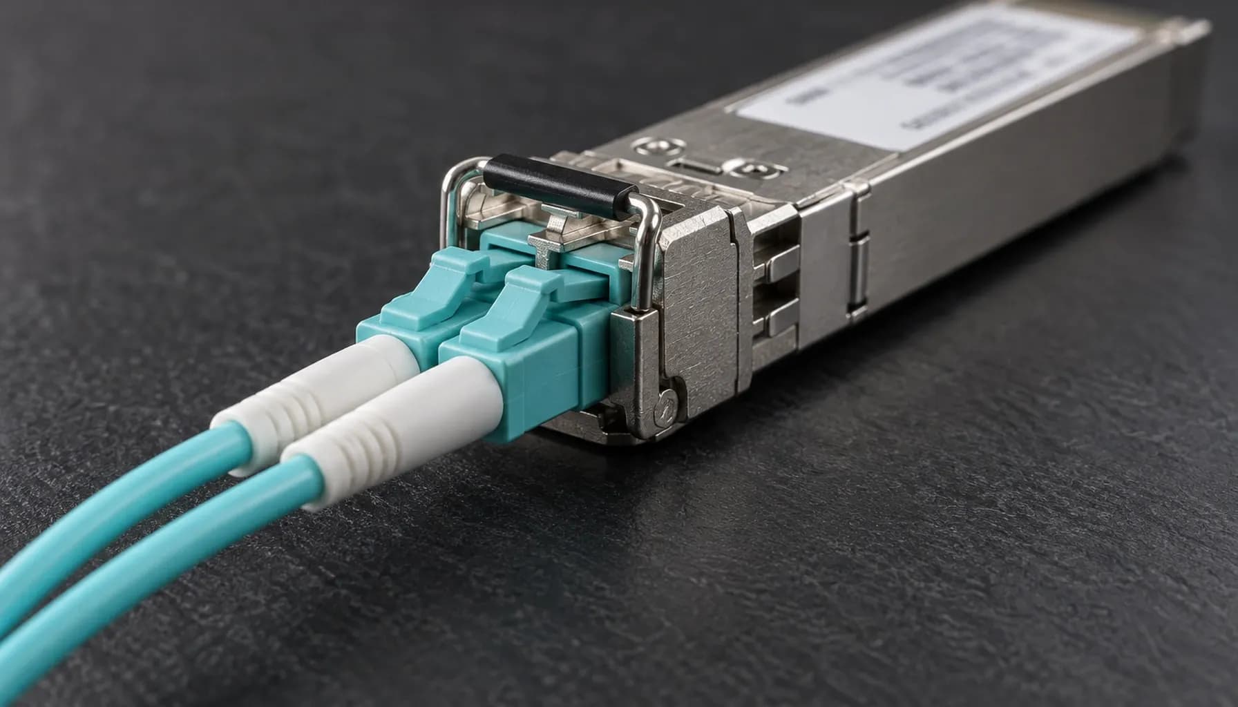
Stomped CRC vs Invalid CRC on 100G Ports: Separating Switch ASIC Faults from Cable and Connector Faults (2026)
100G CRC counters are routinely misclassified as proof of a defective switch ASIC. In UAE high-density deployments, heat, dust, connector contamination, marginal optics, bend stress, EMI, lane imbalance, and unqualified transceivers are more likely causes. Neither “stomped CRC” nor “invalid CRC” identifies where corruption occurred. Both are ingress symptoms; isolation must correlate MAC, FEC, PMD/PCS, DOM, and link-state evidence. CRC Architecture at 100G: What the Counters Actually Mean FCS, FEC, and lane integrity At 100G, Ethernet still uses IEEE 802.3’s CRC-32 frame check sequence (FCS); FCS is not FEC, BER, or a PCS symbol counter. SR4 and ER4 carry frames over four 25G lanes, DR1 over one 100G PAM4 lane, and FR1/LR1 over two 50G PAM4 lanes. FEC can repair physical errors before MAC validation; uncorrectable damage can cause loss, malformed frames, or link faults. CR4 uses four electrical lanes over qualified DAC/ACC. Match the PHY before comparing counters. The 100GBASE PHY Family Decoded: SR4, DR1, FR1, LR1 and ER4 by Lane Architecture, Media and Reach (2026) reference provides the correct media baseline. What “stomped” does—and does not—mean Invalid CRC means the calculated FCS differs from the received FCS. On Nexus 9000 and other Cisco ASIC telemetry, stomped CRC typically counts bad-FCS frames that ingress hardware rejected or marked; the ASIC may be the detector, not the corruption source. Coverage varies by ASIC and release, and platforms may label the same event as CRC, bad CRC, or ingress discard. It is not an IEEE fault class. Connectors, optics, fiber, EMI, endpoint-generated frames, and internal port faults can all produce it. Key takeaway: “Stomped CRC” describes hardware handling of a bad-FCS frame, not the origin of corruption. It is evidence to investigate, never an ASIC diagnosis. High-Density CRC and Physical-Layer Comparison Use this evidence matrix before replacing hardware; no single counter establishes root cause. | Observable | Layer or standard | Meaning or metric | Strong correlation | Leading suspects | Decisive test | |---|---|---|---|---|---| | Invalid CRC | IEEE 802.3 MAC/FCS | Calculated CRC-32 differs from received FCS | Port, frame size, traffic | Endpoint, media, optic, PHY/MAC, ASIC | Connect independently qualified media | | Stomped CRC | Vendor ASIC ingress counter; not IEEE | Bad-FCS frame blocked; label varies by release | Equivalent CRC and ingress-drop counters | Same causes as invalid CRC | Repeat on a known-good port | | FEC corrected | 100GBASE PHY FEC | Correctable physical codewords | Receive power, temperature, EMI, lane | Marginal optic, fiber, connector | Swap the optic | | FEC uncorrectable | 100GBASE PHY FEC | Unrecoverable blocks or symbols | Lane loss, low receive power | Optic, connector, PCS | Inspect, clean, and swap | | LOS or remote fault | PMD and link manager | Link unavailable or remote-side failure | Flaps, temperature, power | Optic, fiber, transceiver | Approved loop or known-good port | | PCS/SERDES errors | PCS and PMD | Symbol, coding, or alignment errors | Specific lane or module | Optic, cable, SerDes | Move the complete module | | Parity, ECC, or internal drops | Switch data path | Internal integrity or resource failure | Ports sharing an ASIC | ASIC, buffer, line card | Two media sets on the same port | Cable and connector evidence A fiber or connector does not need to be visibly broken to fail. Dust, ferrules, contamination, and bend violations can create intermittent lane errors while average DOM readings remain acceptable. Inspect every mating surface with a calibrated scope and clean with approved tools. On CR4 links, verify bend radius and DAC/ACC vendor qualification. Field Isolation Workflow Capture a controlled baseline Label and photograph the path. Capture baseline and counter deltas over a fixed interval under representative traffic; do not clear counters first. Record CRC/stomp, input errors, FEC corrected and uncorrectable, PCS or symbol errors, DOM, temperature, flaps, and internal parity/ECC counters. Confirm media type, lane architecture, reach, firmware, and vendor support. Apply the checks in Pre-Ship Optics Acceptance for 100G Ports: Module-Type, DOM Threshold and Reach Checks (2026) . Inspect the physical layer Use a calibrated inspection scope. Contamination, ferrule damage, bend violations, dirty bulkheads, and EMI are more common than spontaneous fiber failure. Clean with approved tools and never look into a fiber. Healthy DOM does not exclude burst errors or a marginal lane. Use controlled substitutions Test the suspect port with an independently qualified optic and cable, then place the suspect media on a known-good port. If the fault follows the media, that port is not the root cause. If it disappears with clean media, the original path is implicated. If one port fails with two qualified media sets, escalate its PHY, cage, or line card. Moving the link to another line card separates the suspect port from its original ASIC. Never cross-connect fibers outside an approved procedure. Assign cause from correlation One impaired lane, rising FEC, variable or low receive power, and temperature sensitivity point toward optics or connectivity. Identical failures with clean media, multiple ports on one ASIC, internal parity/ECC events, or load-dependent pipeline drops point toward switch hardware or software. Reproduce unicast, multicast, ECMP, VLAN rewrite, oversize, and QoS cases only under change control; load-only failures suggest pipeline behavior but do not alone prove an ASIC fault. Key takeaway: A defensible ASIC case requires persistence on the same port or shared ASIC with qualified media plus corroborating internal evidence. Persistence alone is not causation. Multi-Vendor CLI Evidence Collection Collect read-only evidence first. Command wording changes by platform and release; use ? to confirm support. Archive the same observation window for each platform. NX-OS and IOS XE counter labels are not interchangeable; EOS may expose generic interface errors plus PHY diagnostics; Junos often separates interface, optic, and chassis data. Avoid clear counters until the initial snapshot is complete. Platform and Migration Considerations Cisco Catalyst 9500/9600 IOS XE and Nexus 9000 NX-OS expose CRC and transceiver diagnostics, but CRC and stomped semantics remain ASIC- and release-specific. Arista 7050X3 EOS generally reports interface errors and optical diagnostics rather than Cisco terminology; Juniper QFX5120 Junos separates interface, optic, and chassis diagnostics. Confirm supported optics and releases: a QSFP28 shell proves neither reach nor PHY compatibility. In data center high-speed migration (10g -> 25g -> 100g) troubleshooting diagnostics, use the Data Center High-Speed Migration (10G -> 25G -> 100G): Comprehensive Engineering & Architecture Guide: The Complete UAE Engineering Guide (2026) for staged, module- and lane-aware acceptance. Frequently Asked Questions Does “stomped CRC” prove that the switch ASIC is faulty? No. “Stomped CRC” is a platform-specific count of bad-FCS frames blocked at hardware ingress, not an IEEE category or corruption location. Connectors, optics, fiber, EMI, and endpoint faults can produce it. Diagnose an ASIC only after controlled substitutions reproduce the fault on one port with qualified media and internal evidence corroborate it. Is invalid CRC always a cable problem? No. It states only that received FCS differs from calculated FCS. Causes include endpoint frames, optics, fiber, connectors, PMD/PCS, MAC/PHY, and rarely switch logic. Correlate CRC deltas with FEC, DOM, lane errors, flaps, and substitution results. The CRC counter alone cannot assign physical versus internal root cause. Why can 100G show FEC errors without CRC errors? At 100G, FEC can repair a physical codeword before the MAC sees it. Corrected blocks increment a FEC counter without creating an invalid Ethernet FCS. Beyond correction capacity, blocks may be dropped or malformed frames may reach the MAC, causing CRC errors, loss, or link faults. Rising corrected FEC is an earlier warning than CRC. Should I clean and retest every connector? Record DOM, FEC, CRC, temperature, and power before disturbing the link. Inspect with a calibrated scope, clean correctly, and retest under the same traffic and duration. If the fault follows media to a clean port, external media is implicated. If it remains on one port with two qualified media sets, escalate that port/PHY or line card. When is an ASIC or line-card RMA justified? Require the fault to persist on one port or line card with independently qualified optics, cables, connectors, and firmware while the same media works on a healthy port. Corroborate with internal parity/ECC, buffer, or ingress-drop counters. Multiple failing ports on one ASIC strengthen the case; one CRC counter alone does not justify an RMA. Key Takeaways Preserve CRC, FEC, DOM, temperature, and link-history baselines before swapping or clearing counters. Treat stomped and invalid CRC as symptoms, not component diagnoses. Verify PHY type, lane architecture, reach, DOM limits, firmware, and support. Use suspect-port and known-good-port substitutions before escalation. Require internal parity/ECC or shared-ASIC evidence before an ASIC RMA. Conclusion Keep media, PHY, and switch-data-path evidence separate to make 100G faults tractable. Apply these acceptance gates during 10g-to-25g-to-100g migration, then specify compatible optics, DAC/ACC, and support in the Strinex catalogue .

Categories
Popular Tags
Stomped CRC vs Invalid CRC on 100G Ports: Separating Switch ASIC Faults from Cable and Connector Faults (2026)
100G CRC counters are routinely misclassified as proof of a defective switch ASIC. In UAE high-density deployments, heat, dust, connector contamination, marginal optics, bend stress, EMI, lane imbalance, and unqualified transceivers are more likely causes. Neither “stomped CRC” nor “invalid CRC” identifies where corruption occurred. Both are ingress symptoms; isolation must correlate MAC, FEC, PMD/PCS, DOM, and link-state evidence. CRC Architecture at 100G: What the Counters Actually Mean FCS, FEC, and lane integrity At 100G, Ethernet still uses IEEE 802.3’s CRC-32 frame check sequence (FCS); FCS is not FEC, BER, or a PCS symbol counter. SR4 and ER4 carry frames over four 25G lanes, DR1 over one 100G PAM4 lane, and FR1/LR1 over two 50G PAM4 lanes. FEC can repair physical errors before MAC validation; uncorrectable damage can cause loss, malformed frames, or link faults. CR4 uses four electrical lanes over qualified DAC/ACC. Match the PHY before comparing counters. The 100GBASE PHY Family Decoded: SR4, DR1, FR1, LR1 and ER4 by Lane Architecture, Media and Reach (2026) reference provides the correct media baseline. What “stomped” does—and does not—mean Invalid CRC means the calculated FCS differs from the received FCS. On Nexus 9000 and other Cisco ASIC telemetry, stomped CRC typically counts bad-FCS frames that ingress hardware rejected or marked; the ASIC may be the detector, not the corruption source. Coverage varies by ASIC and release, and platforms may label the same event as CRC, bad CRC, or ingress discard. It is not an IEEE fault class. Connectors, optics, fiber, EMI, endpoint-generated frames, and internal port faults can all produce it. Key takeaway: “Stomped CRC” describes hardware handling of a bad-FCS frame, not the origin of corruption. It is evidence to investigate, never an ASIC diagnosis. High-Density CRC and Physical-Layer Comparison Use this evidence matrix before replacing hardware; no single counter establishes root cause. | Observable | Layer or standard | Meaning or metric | Strong correlation | Leading suspects | Decisive test | |---|---|---|---|---|---| | Invalid CRC | IEEE 802.3 MAC/FCS | Calculated CRC-32 differs from received FCS | Port, frame size, traffic | Endpoint, media, optic, PHY/MAC, ASIC | Connect independently qualified media | | Stomped CRC | Vendor ASIC ingress counter; not IEEE | Bad-FCS frame blocked; label varies by release | Equivalent CRC and ingress-drop counters | Same causes as invalid CRC | Repeat on a known-good port | | FEC corrected | 100GBASE PHY FEC | Correctable physical codewords | Receive power, temperature, EMI, lane | Marginal optic, fiber, connector | Swap the optic | | FEC uncorrectable | 100GBASE PHY FEC | Unrecoverable blocks or symbols | Lane loss, low receive power | Optic, connector, PCS | Inspect, clean, and swap | | LOS or remote fault | PMD and link manager | Link unavailable or remote-side failure | Flaps, temperature, power | Optic, fiber, transceiver | Approved loop or known-good port | | PCS/SERDES errors | PCS and PMD | Symbol, coding, or alignment errors | Specific lane or module | Optic, cable, SerDes | Move the complete module | | Parity, ECC, or internal drops | Switch data path | Internal integrity or resource failure | Ports sharing an ASIC | ASIC, buffer, line card | Two media sets on the same port | Cable and connector evidence A fiber or connector does not need to be visibly broken to fail. Dust, ferrules, contamination, and bend violations can create intermittent lane errors while average DOM readings remain acceptable. Inspect every mating surface with a calibrated scope and clean with approved tools. On CR4 links, verify bend radius and DAC/ACC vendor qualification. Field Isolation Workflow Capture a controlled baseline Label and photograph the path. Capture baseline and counter deltas over a fixed interval under representative traffic; do not clear counters first. Record CRC/stomp, input errors, FEC corrected and uncorrectable, PCS or symbol errors, DOM, temperature, flaps, and internal parity/ECC counters. Confirm media type, lane architecture, reach, firmware, and vendor support. Apply the checks in Pre-Ship Optics Acceptance for 100G Ports: Module-Type, DOM Threshold and Reach Checks (2026) . Inspect the physical layer Use a calibrated inspection scope. Contamination, ferrule damage, bend violations, dirty bulkheads, and EMI are more common than spontaneous fiber failure. Clean with approved tools and never look into a fiber. Healthy DOM does not exclude burst errors or a marginal lane. Use controlled substitutions Test the suspect port with an independently qualified optic and cable, then place the suspect media on a known-good port. If the fault follows the media, that port is not the root cause. If it disappears with clean media, the original path is implicated. If one port fails with two qualified media sets, escalate its PHY, cage, or line card. Moving the link to another line card separates the suspect port from its original ASIC. Never cross-connect fibers outside an approved procedure. Assign cause from correlation One impaired lane, rising FEC, variable or low receive power, and temperature sensitivity point toward optics or connectivity. Identical failures with clean media, multiple ports on one ASIC, internal parity/ECC events, or load-dependent pipeline drops point toward switch hardware or software. Reproduce unicast, multicast, ECMP, VLAN rewrite, oversize, and QoS cases only under change control; load-only failures suggest pipeline behavior but do not alone prove an ASIC fault. Key takeaway: A defensible ASIC case requires persistence on the same port or shared ASIC with qualified media plus corroborating internal evidence. Persistence alone is not causation. Multi-Vendor CLI Evidence Collection Collect read-only evidence first. Command wording changes by platform and release; use ? to confirm support. Archive the same observation window for each platform. NX-OS and IOS XE counter labels are not interchangeable; EOS may expose generic interface errors plus PHY diagnostics; Junos often separates interface, optic, and chassis data. Avoid clear counters until the initial snapshot is complete. Platform and Migration Considerations Cisco Catalyst 9500/9600 IOS XE and Nexus 9000 NX-OS expose CRC and transceiver diagnostics, but CRC and stomped semantics remain ASIC- and release-specific. Arista 7050X3 EOS generally reports interface errors and optical diagnostics rather than Cisco terminology; Juniper QFX5120 Junos separates interface, optic, and chassis diagnostics. Confirm supported optics and releases: a QSFP28 shell proves neither reach nor PHY compatibility. In data center high-speed migration (10g -> 25g -> 100g) troubleshooting diagnostics, use the Data Center High-Speed Migration (10G -> 25G -> 100G): Comprehensive Engineering & Architecture Guide: The Complete UAE Engineering Guide (2026) for staged, module- and lane-aware acceptance. Frequently Asked Questions Does “stomped CRC” prove that the switch ASIC is faulty? No. “Stomped CRC” is a platform-specific count of bad-FCS frames blocked at hardware ingress, not an IEEE category or corruption location. Connectors, optics, fiber, EMI, and endpoint faults can produce it. Diagnose an ASIC only after controlled substitutions reproduce the fault on one port with qualified media and internal evidence corroborate it. Is invalid CRC always a cable problem? No. It states only that received FCS differs from calculated FCS. Causes include endpoint frames, optics, fiber, connectors, PMD/PCS, MAC/PHY, and rarely switch logic. Correlate CRC deltas with FEC, DOM, lane errors, flaps, and substitution results. The CRC counter alone cannot assign physical versus internal root cause. Why can 100G show FEC errors without CRC errors? At 100G, FEC can repair a physical codeword before the MAC sees it. Corrected blocks increment a FEC counter without creating an invalid Ethernet FCS. Beyond correction capacity, blocks may be dropped or malformed frames may reach the MAC, causing CRC errors, loss, or link faults. Rising corrected FEC is an earlier warning than CRC. Should I clean and retest every connector? Record DOM, FEC, CRC, temperature, and power before disturbing the link. Inspect with a calibrated scope, clean correctly, and retest under the same traffic and duration. If the fault follows media to a clean port, external media is implicated. If it remains on one port with two qualified media sets, escalate that port/PHY or line card. When is an ASIC or line-card RMA justified? Require the fault to persist on one port or line card with independently qualified optics, cables, connectors, and firmware while the same media works on a healthy port. Corroborate with internal parity/ECC, buffer, or ingress-drop counters. Multiple failing ports on one ASIC strengthen the case; one CRC counter alone does not justify an RMA. Key Takeaways Preserve CRC, FEC, DOM, temperature, and link-history baselines before swapping or clearing counters. Treat stomped and invalid CRC as symptoms, not component diagnoses. Verify PHY type, lane architecture, reach, DOM limits, firmware, and support. Use suspect-port and known-good-port substitutions before escalation. Require internal parity/ECC or shared-ASIC evidence before an ASIC RMA. Conclusion Keep media, PHY, and switch-data-path evidence separate to make 100G faults tractable. Apply these acceptance gates during 10g-to-25g-to-100g migration, then specify compatible optics, DAC/ACC, and support in the Strinex catalogue .
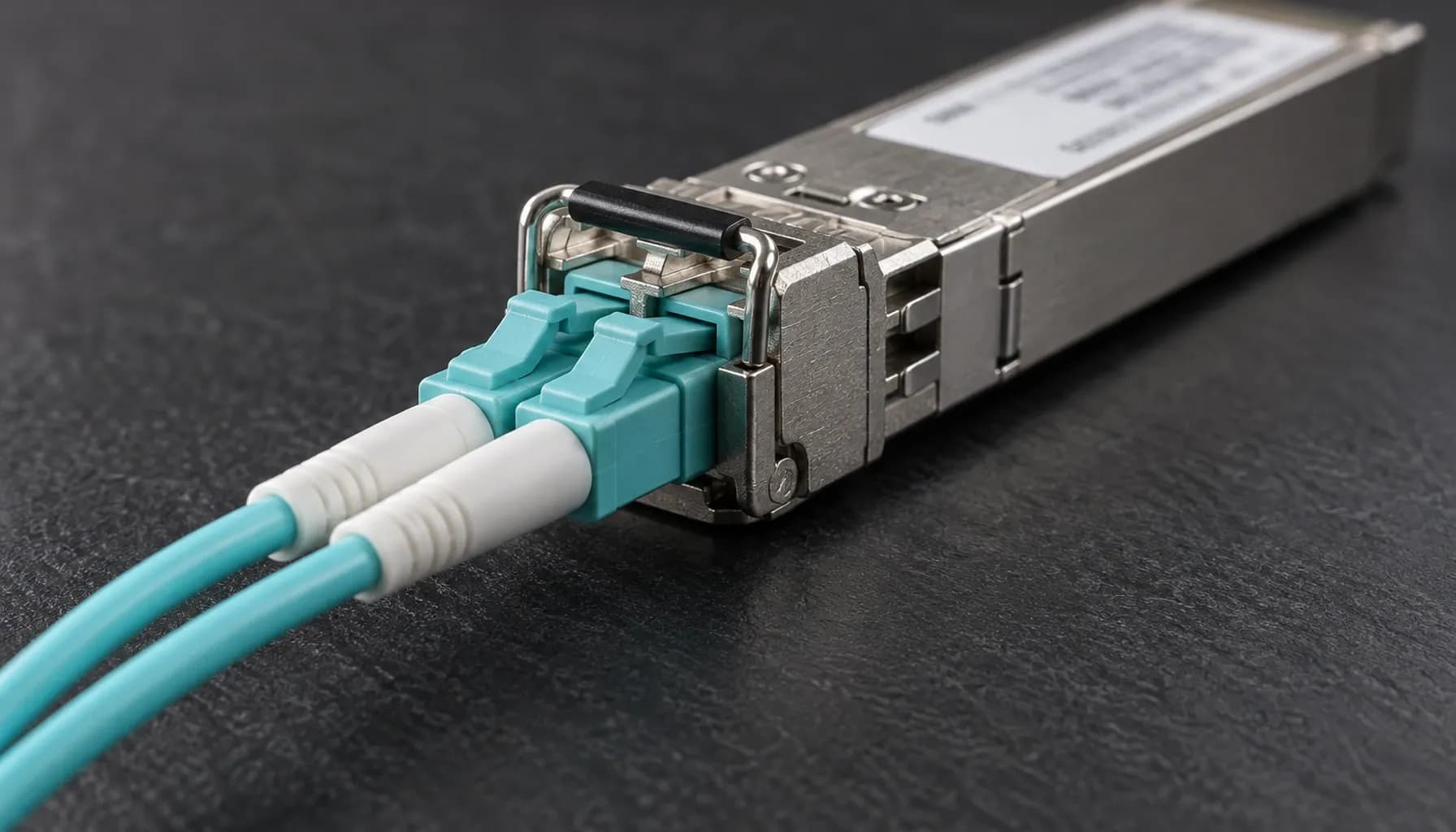
Pre-Ship Optics Acceptance for 100G Ports: Module-Type, DOM Threshold and Reach Checks (2026)
A 100G optic can pass a visual inventory check and still fail deployment because the switch SKU, software train, fiber media, lane architecture, or diagnostic headroom is wrong. In a data center high-speed migration (10g -> 25g -> 100g) installation cli configuration , treat optics as controlled hardware: identity, platform support, path budget, and live DOM must all pass before shipment or rack integration. Acceptance Architecture: Freeze the Deployment Envelope Use four acceptance gates. First, freeze the switch model/SKU, line card, software release, port mode, optic vendor and part number, fiber type, connector, and topology. Second, verify the module in the intended target port. Third, measure the optical path. Fourth, generate representative traffic and compare error-counter deltas. A loopback-only test cannot combine platform and path qualification. Record serial numbers, calibration references, ambient conditions, and pass/fail evidence. Compatibility is not qualification: a QSFP28 enclosure does not establish PHY or vendor support, and breakout changes electrical semantics. Sequence these gates with the wider Data Center High-Speed Migration (10G -> 25G -> 100G): Comprehensive Engineering & Architecture Guide: The Complete UAE Engineering Guide (2026) . 100G Module Comparison: Match PHY, Media and Reach Start with the advertised PHY, then verify the vendor’s supported-part list and platform-specific exceptions. | PHY/module | Standard/profile | Media and lane architecture | Nominal reach | DOM focus | Pre-ship metric | |---|---|---|---|---|---| | 100GBASE-SR4 | IEEE 802.3bm | OM3/OM4/OM5; 4×850 nm | 70 m/100 m | Per-lane or aggregate Tx/Rx, temperature, bias | Lane balance; multimode insertion loss | | 100GBASE-DR1 | IEEE 802.3df-2024 | SMF; 1×1310 nm | 500 m | Tx/Rx, temperature, bias, voltage | End-to-end loss with project margin | | 100GBASE-FR1 | IEEE 802.3df-2024 | SMF; 1×1310 nm | 2 km | Tx/Rx, temperature, bias, voltage | End-to-end loss with project margin | | 100GBASE-LR1 | IEEE 802.3df-2024 | SMF; 1×1310 nm | 10 km | Tx/Rx, temperature, bias, voltage | End-to-end loss with project margin | | 100GBASE-ER4 | IEEE 802.3bm | SMF; 4×1550 nm | 40 km | Per-wavelength or aggregate Tx/Rx, temperature, bias | Channel loss and project margin | Reach is a media-and-implementation property, not a connector promise. Vendor parts may differ in launch power, sensitivity, and firmware behavior; legacy “LR4” is not LR1. For lane-level distinctions, use 100GBASE PHY Family Decoded: SR4, DR1, FR1, LR1 and ER4 by Lane Architecture, Media and Reach (2026) . DOM Threshold Checks: Limits Are Only One Gate Read Limits and Live Values DOM is module telemetry, not a link guarantee. QSFP28 management may expose module-wide or per-lane values under SFF-8431/CMIS conventions; supported fields vary. Read warning and alarm limits alongside current Tx, Rx, bias, voltage, and temperature. Before a valid far-end launch, Rx may be unavailable or zero; record “not measurable,” not “failed.” Apply a Defensible Pass Rule Require the exact supported part number, every measured field inside vendor limits, no active alarm, expected Tx launch level, calculated path margin, successful link, and no attributable CRC/FCS, input, or symbol-error delta. Investigate discards separately. Compare against the module datasheet and supported switch release; never reprogram thresholds to force a pass. Test temperature extremes expected in UAE deployments, not only a cool bench. Key takeaway: DOM compliance is necessary, not sufficient; compatibility, end-to-end budget, and error-free traffic are separate acceptance gates. Multi-Vendor Read and Verification Commands Use read-only commands first; syntax follows the platform and release. Retain full output for the serialized record. Catalyst acceptance must include the exact C9300 SKU, uplink/stack mode, and IOS XE train; Nexus requires the exact N9K platform/line card and NX-OS release; Arista requires the 7050X SKU and EOS; QFX requires the board and Junos combination, such as QFX5120 or QFX5200. “No data” is not a pass. Normalize dBm, timestamps, and lane identifiers, then compare live readings with thresholds and pre/post traffic counters. Reach and Platform Acceptance At 1310 nm, budget fiber attenuation from the cable datasheet—approximately 0.35 dB/km is only a planning figure—then add connectors, splices, patch leads, and aging. At 1550 nm, use actual fiber loss because a generic value can understate it. Require project margin—commonly at least 3 dB—after all losses. Use a calibrated power meter and reference source; DOM at both ends does not replace path measurement. For SR4, test the correct OM grade and inspect all four connectors and lane polarity. For single-mode optics, confirm SMF and matching connector polish; never mix UPC and APC. Validate reach against actual distance, not the module label. Confirm 100G versus 4×25G breakout mode and whether the selected PHY is supported. A port capable of 100G is not automatically compatible with every 100G module. Pre-Ship Evidence and Quarantine Create a serialized FAT/SAT record containing switch and software identity, port, optic part/serial, fiber and patch identifiers, live DOM, programmed limits, optical power, link result, traffic profile, and counter deltas. Photograph contamination, bent pins, or seal damage. Keep nonconforming modules quarantined with the failure reason; do not ship them as “spares.” Repeat identity, DOM, and link checks at rack receipt, then correlate each serial to the asset record. Key takeaway: No module leaves the acceptance flow without a traceable part number, threshold result, link result, and operator disposition. Frequently Asked Questions Is a DOM reading within its limits proof that a 100G optic will pass? No. DOM measures the module, not end-to-end quality. A module can meet its limits yet fail because the path budget is exceeded, a connector is dirty, a lane is mismatched, or the switch rejects its part number. Require supported identity, healthy DOM, a successful link, clean counters, and independent power-meter verification. Can an SR4 module be used in a DR1 port because both use QSFP28? No. QSFP28 describes the envelope and electrical interface, not the optical PHY. SR4 uses four 850-nm lanes over multimode; DR1, FR1, and LR1 use one 1310-nm lane over single-mode. The platform must support the exact module and PHY. A physical fit can still produce no link or an unsupported-module alarm. What received-power margin is acceptable? Use the module’s worst-case specifications and the actual path loss, then retain the project margin—commonly at least 3 dB. Include connector, splice, patch-lead, and aging losses, not just fiber length. Confirm launch and received power with calibrated reference equipment because DOM values from two modules are not an end-to-end measurement. Do DOM thresholds and telemetry vary by vendor? Yes. Limits and telemetry are vendor- and part-specific. QSFP28 management may expose module-wide or per-lane values through SFF-8431/CMIS-style pages, and supported fields vary by platform. Evaluate every warning or unsupported state against the exact part number and switch release. Never alter a threshold to make a failing module appear compliant. Must every optic be tested in every target switch? No. Test every optic on representative target hardware and software; use a controlled sampling plan for repeated identical batches when the SLA permits. The batch record must retain serial numbers, firmware, ports, DOM values, link results, and counter deltas. Any lot-level exception should trigger expanded testing or quarantine. Key Takeaways Freeze an approved matrix linking switch SKU, release, port mode, optic part number, media, and reach. Require serialized identity, visual inspection, DOM readings, and supported-module status for every optic. Measure each path with calibrated equipment and retain project optical margin; do not infer budget from nominal reach. Run link and representative traffic tests, preserve counter deltas, and quarantine every exception. Qualify for UAE ambient temperature, dust, connector contamination, and lead-time risk before bulk shipment. Conclusion Pre-ship acceptance must produce one auditable answer: this exact optic is supported by this switch release, healthy at the link, and operating within the installed path’s budget. Source compatible 100G optics, supported switch hardware, and test equipment through the Strinex catalogue .
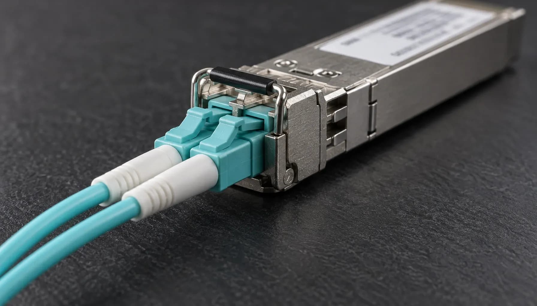
100GBASE PHY Family Decoded: SR4, DR1, FR1, LR1 and ER4 by Lane Architecture, Media and Reach (2026)
The 100G Migration Decision: Lane Architecture Is the First Design Constraint A 100Gb/s uplink is not one optical technology. It is a family of implementations with materially different lane counts, fibre types, laser designs, reach, power budgets, and transceiver requirements. In a data center high-speed migration (10g -> 25g -> 100g), the practical choice is rarely “100G versus non-100G”; it is whether the target fabric requires multimode or single-mode connectivity, four parallel lanes or one high-speed lane, and short rack-room reach or a 10–40 km campus/building span. SR4, DR1, FR1, LR1 and ER4 therefore must be evaluated as an architecture rather than as interchangeable QSFP28 labels. The distinction becomes operationally important when deploying across Cisco Catalyst and Nexus platforms, Arista 7050X switches, and Juniper QFX systems, where optics validation, interface breakout behaviour, and transceiver diagnostics can differ by platform and software release. The broader migration context is covered in the Data Center High-Speed Migration (10G -> 25g -> 100G): Comprehensive Engineering & Architecture Guide: The Complete UAE Engineering Guide (2026) . PHY Family Comparison: Specifications That Change the Design The following table compares the principal members of the 100GBASE PHY family. “Lane” refers to the high-speed optical lanes presented by the module; it does not necessarily mean that every implementation uses identical electrical signalling. | PHY | IEEE reference | Optical architecture | Media | Typical reach | Fibre and connector implication | |---|---|---|---|---|---| | 100GBASE-SR4 | IEEE 802.3bm | 4 × 25Gb/s, 850 nm VCSEL, NRZ | OM3/OM4 multimode | Up to 100 m | Four parallel optical paths; commonly used for short data-center links | | 100GBASE-DR1 | IEEE 802.3cu family | 1 × 100Gb/s, 1310 nm, PAM4 | OM4 multimode or single-mode variants | 500 m MMF; SMF options may reach 10 km | One high-speed lane; avoids four-lane parallel optics | | 100GBASE-FR1 | IEEE 802.3cu | 1 × 100Gb/s, 1310 nm, PAM4 | Single-mode fibre | 2 km | Low-cost single-mode option for building or campus aggregation | | 100GBASE-LR1 | IEEE 802.3cu | 1 × 100Gb/s, 1310 nm, PAM4 | Single-mode fibre | 10 km | Single-lane reach for longer intra-campus or metropolitan links | | 100GBASE-ER4 | IEEE 802.3ba | 4 × 25Gb/s, 1310 nm wavelength set, NRZ | Single-mode fibre | 40 km | Four wavelengths over one duplex fibre pair; larger optical budget | Key takeaway: SR4 is a parallel multimode architecture; DR1, FR1 and LR1 are single-lane 1310 nm single-mode-oriented designs; ER4 is a four-wavelength single-mode architecture. The PHY label must be matched to the actual fibre path, not selected from reach alone. SR4: Low Latency Inside the Data Center SR4 uses four 25Gb/s lanes, normally at 850 nm over OM3 or OM4 multimode fibre. Its principal advantage is maturity and broad availability of 100G QSFP28 modules. The trade-off is the requirement for four optical lanes and the need to maintain multimode fibre quality, connector cleanliness, and bend radius. SR4 is appropriate for short server-to-switch or switch-to-switch connections where both ends are inside the same data hall or closely controlled row. It is less attractive for a long campus route because multimode is generally unavailable beyond the optical budget, and fibre transitions add engineering risk. In a migration from 10G or 25G, SR4 can provide a straightforward QSFP28 endpoint while retaining a familiar fibre infrastructure. DR1, FR1 and LR1: The Single-Lane 100G Choices The single-lane family uses 100Gb/s PAM4 at approximately 1310 nm. PAM4 doubles the signalling rate relative to NRZ, improving spectral efficiency and allowing a single optical lane to carry the full 100G payload. The associated transceiver and electronics are more demanding than 25G NRZ, but the fibre path becomes simpler than a four-lane SR4 or ER4 deployment. FR1 is the usual starting point for 2 km single-mode links. LR1 extends the same broad architecture to 10 km. DR1 is primarily associated with 500 m multimode connectivity and may also be specified in single-mode variants; procurement should therefore confirm the exact cable and module variant rather than relying on the PHY name. Key takeaway: For new single-mode infrastructure, FR1 at 2 km or LR1 at 10 km usually provides a cleaner path than SR4. Confirm whether the design requires multimode compatibility before standardising DR1. ER4: Four Wavelengths for Long-Reach Single Mode ER4 carries 100Gb/s across four 25Gb/s wavelengths over a duplex single-mode pair, with an optical reach of approximately 40 km. It is not simply “four SR4 lanes”: the wavelengths are combined and separated through wavelength-division multiplexing components, and the module presents one duplex optical interface. ER4 is relevant when a 40 km route is required but a 400G or newer single-lane ecosystem is not yet justified. Its disadvantages include a more complex and generally more expensive optical assembly, and the need to ensure that the complete path—including patch panels, connectors, splices and any intermediate optical devices—meets the module’s link budget. How the PHY Choice Affects Switch Interoperability The switch model alone does not guarantee interoperability. The combination of ASIC, port type, breakout configuration, firmware, optics vendor, and software release determines whether a QSFP28 module will train correctly. Cisco Nexus 9000 and Catalyst 9500 platforms may expose 100G ports directly or through breakout-capable ports, while Arista 7050X implementations may use QSFP28 interfaces with configuration constraints. Juniper QFX platforms also vary by line card and software train. A conservative migration process is: Verify the exact port hardware and supported optic matrix. Confirm that the transceiver is supported, or explicitly permit a qualified third-party optic. Match the optic to the cable type and measured reach. Validate the link with the intended media, temperature and firmware combination. Record diagnostics and failure signatures before rolling the change to production. Illustrative Multi-Vendor Validation Block The following commands are representative validation steps, not universal deployment recipes. Command syntax must be adapted to the specific platform, line card and release. On Nexus devices, the exact interface naming and breakout commands differ between Ethernet and Ethernet1/1 forms. On Arista, speed 100gfull is normally applied to a dedicated 100G interface; attempting to use it on a breakout member may be rejected. Juniper port names are line-card dependent, and some platforms require an explicit interface-mode or transceiver configuration. Always inspect the platform command reference and supported optic list before configuring. Key takeaway: Treat transceiver interoperability as a tested interface contract. A module may be electrically compatible yet unsupported by the switch image, breakout configuration, or optic-management policy. Deployment Guidance for UAE Data Centers When to Choose SR4 Choose SR4 when the link is short, the existing infrastructure is OM3/OM4, and the operational objective is a low-complexity 100G upgrade using mature QSFP28 hardware. Validate connector cleanliness and ensure that the fibre route does not introduce undocumented patch-panel or bend-radius losses. When to Choose FR1 or LR1 Choose FR1 for 2 km single-mode routes and LR1 for 10 km routes. These options are generally preferable for data-hall-to-data-hall, building-to-building, or campus aggregation where the organisation wants a single optical lane and a clear path toward higher-speed single-lane designs. The 1310 nm window is also operationally useful because many single-mode systems already operate in that window. Nevertheless, the transceiver’s specified launch power, receiver sensitivity and link budget remain decisive. Do not infer compatibility from wavelength alone. When to Choose ER4 Choose ER4 only where the route genuinely approaches 40 km or where the design requires the four-wavelength optical model. For shorter distances, ER4 may add unnecessary cost and complexity. Its physical reach is also not equivalent to guaranteed service distance: every splice, connector, patch lead and optical amplifier changes the engineering margin. Migration and Power Considerations A 10G-to-25G-to-100G programme should not treat optics as the final step. Port density, switch backplane capacity, queueing behaviour, buffer requirements, telemetry, and thermal load can determine whether the migration succeeds. High-density 100G ports can also affect power and cooling in Dubai or Abu Dhabi installations, especially where the design uses fanless equipment or restricted airflow. The power implications of adjacent infrastructure should be assessed alongside the migration. For example, legacy PoE platforms may require an explicit IEEE 802.3bt enablement procedure, including the power-cycle behaviour described in the Enabling IEEE 802.3bt Mode on a Legacy PoE Switch: hw-module switch upoe-plus, the Power-Cycle It Triggers and How to Revert Safely (2026) guide. If a 100G migration is bundled with a PoE refresh, the PSE budget should be modelled rather than estimated; the Cost per 90W Port: PSE Chassis, Expansion Modules and the 15–20% Budget Headroom You Are Paying For (2026) analysis explains the required headroom. Frequently Asked Questions Is SR4 compatible with single-mode fibre? No. SR4 is designed for multimode fibre, principally OM3 or OM4, because its 850 nm VCSEL output and four-lane optical architecture depend on the fibre’s modal characteristics. Using it over single-mode may produce insufficient received power or unstable operation. For single-mode routes, specify an appropriate FR1, LR1, DR1 variant or ER4 module, then confirm the exact transceiver and cable specification. Is DR1 the same as FR1? They are related single-lane, 1310 nm PAM4 technologies, but they are not interchangeable procurement labels. DR1 is generally associated with short-reach multimode connectivity, while FR1 is defined for approximately 2 km over single-mode fibre. Compatibility depends on the transceiver variant, media, switch support matrix and fibre installation. Always verify the exact module, optics and reach rather than treating the names as equivalent. Can a 25G optical link be upgraded by replacing the module? Not automatically. The switch port, ASIC lane configuration, breakout mode, cable and transceiver must all support 100G. A 25G SFP28 port generally cannot accept a 100G QSFP28 module, and a 100G port may require a specific breakout or speed configuration. On Cisco, Arista and Juniper platforms, check the hardware and release documentation, then validate the optic through the switch’s diagnostics commands before production deployment. Which PHY is best for a 10 km campus link? LR1 is the natural starting point for a 10 km single-mode route because it uses a single 100Gb/s lane and is intended for approximately 10 km reach. ER4 can support longer spans, but it introduces a four-wavelength optical architecture and should be selected only when the route or design case requires it. Confirm link budget, splice count, connector quality and transceiver support before selecting the final PHY. Does ER4 require four fibre pairs? No. ER4 presents one duplex optical connection, but internally multiplexes four wavelengths over the single fibre pair. It is therefore physically simpler at the patch-panel level than SR4, which requires four parallel optical lanes and corresponding fibre channels. The transceiver is more complex than a single-lane module, however, and the complete single-mode path must satisfy the specified optical budget. Key Takeaways Select SR4 for mature short-reach multimode links, not as a default 100G architecture. Use FR1 or LR1 for new single-mode routes, with DR1 reserved for verified short-reach variants. Reserve ER4 for genuine long-reach requirements where the four-wavelength design is justified. Validate optics, firmware, breakout mode, fibre length and link budget on each Cisco, Arista and Juniper platform. Include thermal, PoE, telemetry and fibre documentation in the 10G -> 25G -> 100G migration acceptance criteria. Conclusion A disciplined 100G design starts with lane architecture, media and reach—not the QSFP28 form factor alone. Review the Strinex catalogue for compatible 100G optics, validated switch configurations, and UAE-ready data-center deployment components before placing your procurement order.
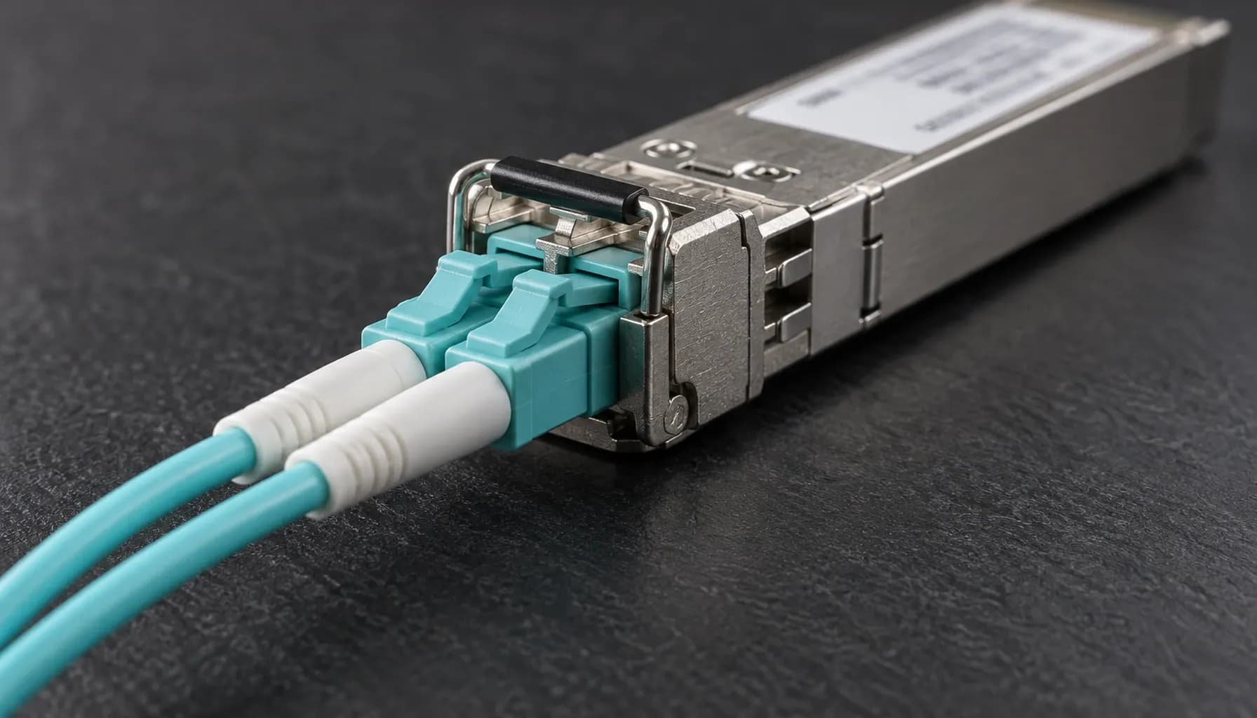
Data Center High-Speed Migration (10G -> 25G -> 100G): Comprehensive Engineering & Architecture Guide: The Complete UAE Engineering Guide (2026)
Data Center High-Speed Migration (10G -> 25G -> 100G): Comprehensive Engineering & Architecture Guide: The Complete UAE Engineering Guide (2026) Introduction: The Imperative of High-Speed Migration in UAE Data Centers In the rapidly evolving landscape of the UAE, where data centers are pivotal to the digital economy, the transition from 10G to 25G and subsequently to 100G is not merely an upgrade but a strategic necessity. This migration is driven by the exponential growth in data traffic, the proliferation of IoT devices, and the increasing demand for low-latency, high-bandwidth applications. This guide provides a comprehensive roadmap for engineering and architecture professionals to navigate this complex migration process, focusing on real-world deployments involving Cisco Catalyst/Nexus, Arista 7050X, and Juniper QFX switches. 1. Assessing the Current Infrastructure and Planning the Migration Evaluating Existing 10G Deployments Before embarking on the migration journey, a thorough assessment of the current 10G infrastructure is crucial. This involves: Inventory Analysis : Identify all 10G switches, modules, and cabling. Document the existing network topology and traffic patterns. Performance Metrics : Analyze bandwidth utilization, latency, and throughput to determine the current performance bottlenecks. Compatibility Check : Ensure that the existing cabling infrastructure (e.g., Cat6a, OM3/OM4) can support higher speeds or plan for necessary upgrades. Key takeaway: A comprehensive inventory and performance analysis are foundational to a successful migration strategy. Developing a Migration Plan The migration plan should be phased, starting with a pilot deployment to validate the new architecture. Key considerations include: Phased Approach : Begin with non-critical segments to minimize disruption. Redundancy and Failover : Ensure that failover mechanisms are in place to maintain network availability during the transition. Budget Allocation : Allocate resources for both hardware and potential downtime. 2. Transitioning from 10G to 25G: Technologies and Considerations Understanding 25G Technology 25G Ethernet offers a cost-effective upgrade path from 10G, providing 2.5 times the bandwidth with minimal changes to the existing infrastructure. Key features include: Backwards Compatibility : 25G switches often support 10G, allowing for gradual migration. Power Efficiency : Improved power efficiency compared to 40G, making it suitable for high-density deployments. Deployment Strategies Leaf-Spine Architecture : Implementing a leaf-spine architecture can enhance scalability and reduce latency. This involves deploying 25G switches at the leaf layer and 100G switches at the spine layer. High-Density Switches : Utilize high-density 25G switches such as the Arista 7050X or Cisco Nexus 93180YC-EX to maximize port utilization. Multi-Vendor Switch Compatibility When deploying multi-vendor switches, ensure compatibility in terms of: Port Speeds and Protocols : Verify that all switches support the required port speeds and protocols. Management Interfaces : Ensure that the management interfaces are compatible for seamless integration. CLI Configuration Example Key takeaway: Multi-vendor compatibility is essential for a smooth transition. Standardizing on common protocols and ensuring CLI consistency can mitigate potential issues. 3. Scaling to 100G: Architectures and Best Practices Architectures for 100G Deployment Transitioning to 100G requires a robust architecture to handle the increased bandwidth. Key architectures include: Spine-Leaf with 100G Spine : Deploying 100G switches at the spine layer provides the necessary backbone for high-speed traffic. 100G Uplinks : Utilize 100G uplinks to connect data center pods and ensure high availability. Best Practices Cable Management : Implement structured cabling practices to manage the complexity of 100G connections. Thermal Management : 100G switches generate significant heat. Ensure adequate cooling solutions are in place. Redundancy : Implement redundant power supplies and failover mechanisms to enhance reliability. High-Density Comparison Table | Feature | Cisco Nexus 93180YC-EX | Arista 7050X | Juniper QFX 10002-36Q | |------------------------|------------------------|--------------|-----------------------| | Port Density | 48 x 25G/10G SFP28 | 32 x 100G | 36 x 100G | | Throughput | 3.6 Tbps | 2.56 Tbps | 7.2 Tbps | | Latency | 350 ns | 450 ns | 300 ns | | Power Consumption | 350W | 300W | 500W | | Form Factor | 1U | 1U | 2U | | Supported Protocols| BGP, OSPF, VXLAN | BGP, OSPF, VXLAN | BGP, OSPF, EVPN | Key takeaway: Selecting the right switch based on port density, throughput, and power consumption is critical for 100G deployment. 4. Ensuring Seamless Integration and Testing Integration Strategies Network Management Systems (NMS) : Utilize NMS to monitor and manage the new infrastructure. Ensure that the NMS supports the new switches and protocols. Configuration Management : Implement configuration management tools to automate and standardize configurations across the network. Testing and Validation Performance Testing : Conduct thorough performance testing to validate the new architecture. Use tools like iPerf or Cisco Prime for benchmarking. Failure Testing : Simulate failure scenarios to test failover mechanisms and ensure high availability. Documentation and Training Documentation : Maintain detailed documentation of the new architecture, configurations, and procedures. Training : Provide training for the operations team to ensure they are proficient in managing the new infrastructure. Key takeaway: Seamless integration and rigorous testing are vital to the success of the migration. Proper documentation and training ensure that the operations team can manage the new environment effectively. Conclusion: Navigating the Future of Data Center Networking in the UAE The migration from 10G to 25G and ultimately to 100G is a complex yet essential undertaking for data centers in the UAE. By following a structured approach that includes thorough planning, careful selection of technologies, and meticulous execution, organizations can achieve a successful transition. This guide provides a comprehensive framework to navigate this journey, ensuring that data centers are equipped to meet the demands of the digital age. --- This guide is designed to be a practical resource for engineers and architects in the UAE, providing actionable insights and best practices for a successful data center high-speed migration. For the lane-by-lane breakdown of the the 10G to 25G to 100G migration architecture that underpins these deployments, see our companion guide.