Our Blog
STRINEX advances eco-friendly technologies, reducing fossil fuel reliance and supporting sustainable living. Our mission is to lead renewable energy and sustainable infrastructure through innovation and efficiency.
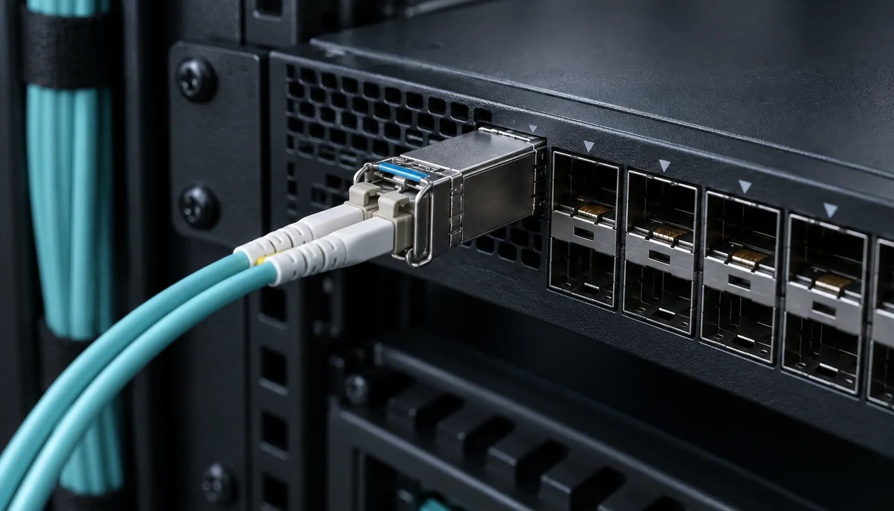
Strinex Engineer's Handbook: Troubleshooting Single-Mode (OS2) vs Multi-Mode (OM3/OM4) - From DOM Alarms to OTDR Event Analysis on Cisco, Arista & Juniper
Strinex Engineer's Handbook: Troubleshooting Single-Mode (OS2) vs Multi-Mode (OM3/OM4) - From DOM Alarms to OTDR Event Analysis on Cisco, Arista & Juniper When deploying fiber-optic networks in enterprise environments, choosing between single-mode (OS2) and multi-mode (OM3/OM4) fiber is a critical decision that impacts network performance, cost, and scalability. This handbook provides a comprehensive guide for troubleshooting these fiber types, focusing on real-world deployment scenarios involving Cisco Catalyst/Nexus, Arista 7050X, and Juniper QFX switches. We will delve into distance limitations, loss management, cost considerations, and diagnostic tools like DOM (Digital Optical Monitoring) and OTDR (Optical Time-Domain Reflectometer). 1. Distance and Loss: Understanding the Fundamentals Single-Mode vs Multi-Mode: Distance Capabilities Single-mode (OS2) fiber is designed for long-distance transmission, typically supporting up to 10 km or more depending on the transceiver type and data rate. In contrast, multi-mode (OM3/OM4) fiber is optimized for shorter distances, with OM3 supporting up to 300 meters and OM4 up to 550 meters at 10 Gbps. Key Factors Affecting Distance: Attenuation: OS2 fiber has lower attenuation (typically 0.4 dB/km) compared to OM3/OM4 (3 dB/km for OM3 and 2.3 dB/km for OM4). Modal Dispersion: Multi-mode fiber suffers from modal dispersion, which limits its effective distance, especially at higher data rates. Loss Budget Management Loss budget is a critical consideration when designing fiber links. It is the maximum amount of signal loss that a fiber link can tolerate while maintaining reliable performance. Loss Budget Calculation: Transceiver Launch Power: The power at which the signal is transmitted. Receiver Sensitivity: The minimum power required for the receiver to detect the signal. Connector and Splice Losses: Typically 0.5 dB per connector and 0.1 dB per splice. Example Loss Budget Calculation: For a 10 Gbps link using OM3 fiber with a transceiver launch power of -5 dBm and a receiver sensitivity of -14 dBm: Total Loss Budget: 9 dB Allowable Loss: 9 dB - (0.5 dB x 2 connectors) - (0.1 dB x 2 splices) = 8.3 dB Key takeaway: Single-mode fiber offers superior distance capabilities and lower attenuation, making it ideal for long-haul applications, while multi-mode fiber is cost-effective for shorter distances in enterprise environments. 2. Cost Considerations: Balancing Performance and Budget Upfront Costs vs Long-Term Savings While single-mode fiber components are generally more expensive than multi-mode counterparts, the total cost of ownership (TCO) should be considered. Cost Factors: Fiber Cable Costs: Multi-mode cables are typically cheaper than single-mode. Transceiver Costs: Single-mode transceivers are more expensive due to the more complex laser technology required. Installation Costs: Single-mode fiber requires more precise alignment and handling, potentially increasing installation costs. Future-Proofing: Investing in single-mode infrastructure can be more cost-effective in the long run, especially for networks expecting growth or higher data rates. Comparative Cost Analysis | Specification | Single-Mode (OS2) | Multi-Mode (OM3) | Multi-Mode (OM4) | |---------------------|--------------------|-------------------|-------------------| | **Cable Cost per Meter** | Higher | Lower | Lower | | **Transceiver Cost** | Higher | Lower | Lower | | **Installation Complexity** | Higher | Lower | Lower | | **Distance Capability** | Up to 10 km+ | Up to 300 m | Up to 550 m | | **Attenuation** | 0.4 dB/km | 3 dB/km | 2.3 dB/km | | **Modal Dispersion** | Negligible | Significant | Significant | Key takeaway: While single-mode fiber has higher upfront costs, its superior performance and scalability can lead to long-term savings, especially for networks requiring high bandwidth and long distances. 3. DOM Alarms and Troubleshooting Understanding DOM Alarms DOM (Digital Optical Monitoring) is a feature in modern transceivers that provides real-time monitoring of optical parameters such as transmit power, receive power, and temperature. Common DOM Alarms: High Transmit Power: Indicates the laser is operating above the specified power level. Low Receive Power: Suggests signal loss or attenuation issues. High Temperature: Can lead to performance degradation or transceiver failure. Troubleshooting Steps Check Transceiver Compatibility: Ensure the transceiver is compatible with the switch and fiber type. Verify Fiber Connections: Inspect for dirty or damaged connectors and ensure proper alignment. Review DOM Data: Use the switch's CLI to monitor DOM parameters and identify anomalies. Isolate the Issue: Disconnect the fiber at various points to isolate the source of the problem. CLI Configuration Example Cisco Catalyst/Nexus: Arista 7050X: Juniper QFX: Key takeaway: DOM provides valuable insights into transceiver performance, enabling proactive troubleshooting and maintenance. 4. OTDR Event Analysis and Interpretation OTDR Basics OTDR (Optical Time-Domain Reflectometer) is a diagnostic tool used to analyze fiber links by sending pulses of light and measuring the reflections. Interpreting OTDR Traces Fiber End: A strong reflection indicates the end of the fiber. Connectors and Splices: Reflective events with varying amplitudes. Bends and Breaks: Non-reflective events with high loss. Ghosts: False reflections that can be identified by their consistent spacing. Troubleshooting with OTDR Identify Reflective Events: Use OTDR traces to locate connectors, splices, and fiber ends. Analyze Loss Values: Compare measured losses with expected values to identify anomalies. Detect Non-Reflective Events: Identify bends, breaks, or other issues causing signal loss. Validate Fiber Integrity: Ensure the fiber is free from major defects or damage. OTDR Trace Example ! OTDR Trace Example Key takeaway: OTDR is an essential tool for diagnosing fiber issues, providing detailed insights into the health and integrity of the fiber infrastructure. 5. Multi-Vendor Switch Compatibility and CLI Configuration Ensuring Compatibility When working with multi-vendor environments, it is crucial to ensure that transceivers and switches are compatible. CLI Configuration Examples Cisco Catalyst/Nexus: Arista 7050X: Juniper QFX: Vendor Lock Commands Cisco: Arista: Juniper: Key takeaway: Multi-vendor environments require careful configuration and compatibility checks to ensure seamless interoperability. Conclusion Troubleshooting single-mode (OS2) and multi-mode (OM3/OM4) fiber involves a deep understanding of distance, loss, cost, and diagnostic tools. By leveraging DOM alarms and OTDR event analysis, network engineers can proactively identify and resolve issues, ensuring optimal network performance. For more detailed guidance on wiring, CLI verification, and vendor lock commands, refer to our Single-Mode (OS2) vs Multi-Mode (OM3/OM4) Wiring & CLI Verification Cheat-Sheet .
Categories
Popular Tags

Strinex Engineer's Handbook: Troubleshooting Single-Mode (OS2) vs Multi-Mode (OM3/OM4) - From DOM Alarms to OTDR Event Analysis on Cisco, Arista & Juniper
Strinex Engineer's Handbook: Troubleshooting Single-Mode (OS2) vs Multi-Mode (OM3/OM4) - From DOM Alarms to OTDR Event Analysis on Cisco, Arista & Juniper When deploying fiber-optic networks in enterprise environments, choosing between single-mode (OS2) and multi-mode (OM3/OM4) fiber is a critical decision that impacts network performance, cost, and scalability. This handbook provides a comprehensive guide for troubleshooting these fiber types, focusing on real-world deployment scenarios involving Cisco Catalyst/Nexus, Arista 7050X, and Juniper QFX switches. We will delve into distance limitations, loss management, cost considerations, and diagnostic tools like DOM (Digital Optical Monitoring) and OTDR (Optical Time-Domain Reflectometer). 1. Distance and Loss: Understanding the Fundamentals Single-Mode vs Multi-Mode: Distance Capabilities Single-mode (OS2) fiber is designed for long-distance transmission, typically supporting up to 10 km or more depending on the transceiver type and data rate. In contrast, multi-mode (OM3/OM4) fiber is optimized for shorter distances, with OM3 supporting up to 300 meters and OM4 up to 550 meters at 10 Gbps. Key Factors Affecting Distance: Attenuation: OS2 fiber has lower attenuation (typically 0.4 dB/km) compared to OM3/OM4 (3 dB/km for OM3 and 2.3 dB/km for OM4). Modal Dispersion: Multi-mode fiber suffers from modal dispersion, which limits its effective distance, especially at higher data rates. Loss Budget Management Loss budget is a critical consideration when designing fiber links. It is the maximum amount of signal loss that a fiber link can tolerate while maintaining reliable performance. Loss Budget Calculation: Transceiver Launch Power: The power at which the signal is transmitted. Receiver Sensitivity: The minimum power required for the receiver to detect the signal. Connector and Splice Losses: Typically 0.5 dB per connector and 0.1 dB per splice. Example Loss Budget Calculation: For a 10 Gbps link using OM3 fiber with a transceiver launch power of -5 dBm and a receiver sensitivity of -14 dBm: Total Loss Budget: 9 dB Allowable Loss: 9 dB - (0.5 dB x 2 connectors) - (0.1 dB x 2 splices) = 8.3 dB Key takeaway: Single-mode fiber offers superior distance capabilities and lower attenuation, making it ideal for long-haul applications, while multi-mode fiber is cost-effective for shorter distances in enterprise environments. 2. Cost Considerations: Balancing Performance and Budget Upfront Costs vs Long-Term Savings While single-mode fiber components are generally more expensive than multi-mode counterparts, the total cost of ownership (TCO) should be considered. Cost Factors: Fiber Cable Costs: Multi-mode cables are typically cheaper than single-mode. Transceiver Costs: Single-mode transceivers are more expensive due to the more complex laser technology required. Installation Costs: Single-mode fiber requires more precise alignment and handling, potentially increasing installation costs. Future-Proofing: Investing in single-mode infrastructure can be more cost-effective in the long run, especially for networks expecting growth or higher data rates. Comparative Cost Analysis | Specification | Single-Mode (OS2) | Multi-Mode (OM3) | Multi-Mode (OM4) | |---------------------|--------------------|-------------------|-------------------| | **Cable Cost per Meter** | Higher | Lower | Lower | | **Transceiver Cost** | Higher | Lower | Lower | | **Installation Complexity** | Higher | Lower | Lower | | **Distance Capability** | Up to 10 km+ | Up to 300 m | Up to 550 m | | **Attenuation** | 0.4 dB/km | 3 dB/km | 2.3 dB/km | | **Modal Dispersion** | Negligible | Significant | Significant | Key takeaway: While single-mode fiber has higher upfront costs, its superior performance and scalability can lead to long-term savings, especially for networks requiring high bandwidth and long distances. 3. DOM Alarms and Troubleshooting Understanding DOM Alarms DOM (Digital Optical Monitoring) is a feature in modern transceivers that provides real-time monitoring of optical parameters such as transmit power, receive power, and temperature. Common DOM Alarms: High Transmit Power: Indicates the laser is operating above the specified power level. Low Receive Power: Suggests signal loss or attenuation issues. High Temperature: Can lead to performance degradation or transceiver failure. Troubleshooting Steps Check Transceiver Compatibility: Ensure the transceiver is compatible with the switch and fiber type. Verify Fiber Connections: Inspect for dirty or damaged connectors and ensure proper alignment. Review DOM Data: Use the switch's CLI to monitor DOM parameters and identify anomalies. Isolate the Issue: Disconnect the fiber at various points to isolate the source of the problem. CLI Configuration Example Cisco Catalyst/Nexus: Arista 7050X: Juniper QFX: Key takeaway: DOM provides valuable insights into transceiver performance, enabling proactive troubleshooting and maintenance. 4. OTDR Event Analysis and Interpretation OTDR Basics OTDR (Optical Time-Domain Reflectometer) is a diagnostic tool used to analyze fiber links by sending pulses of light and measuring the reflections. Interpreting OTDR Traces Fiber End: A strong reflection indicates the end of the fiber. Connectors and Splices: Reflective events with varying amplitudes. Bends and Breaks: Non-reflective events with high loss. Ghosts: False reflections that can be identified by their consistent spacing. Troubleshooting with OTDR Identify Reflective Events: Use OTDR traces to locate connectors, splices, and fiber ends. Analyze Loss Values: Compare measured losses with expected values to identify anomalies. Detect Non-Reflective Events: Identify bends, breaks, or other issues causing signal loss. Validate Fiber Integrity: Ensure the fiber is free from major defects or damage. OTDR Trace Example ! OTDR Trace Example Key takeaway: OTDR is an essential tool for diagnosing fiber issues, providing detailed insights into the health and integrity of the fiber infrastructure. 5. Multi-Vendor Switch Compatibility and CLI Configuration Ensuring Compatibility When working with multi-vendor environments, it is crucial to ensure that transceivers and switches are compatible. CLI Configuration Examples Cisco Catalyst/Nexus: Arista 7050X: Juniper QFX: Vendor Lock Commands Cisco: Arista: Juniper: Key takeaway: Multi-vendor environments require careful configuration and compatibility checks to ensure seamless interoperability. Conclusion Troubleshooting single-mode (OS2) and multi-mode (OM3/OM4) fiber involves a deep understanding of distance, loss, cost, and diagnostic tools. By leveraging DOM alarms and OTDR event analysis, network engineers can proactively identify and resolve issues, ensuring optimal network performance. For more detailed guidance on wiring, CLI verification, and vendor lock commands, refer to our Single-Mode (OS2) vs Multi-Mode (OM3/OM4) Wiring & CLI Verification Cheat-Sheet .
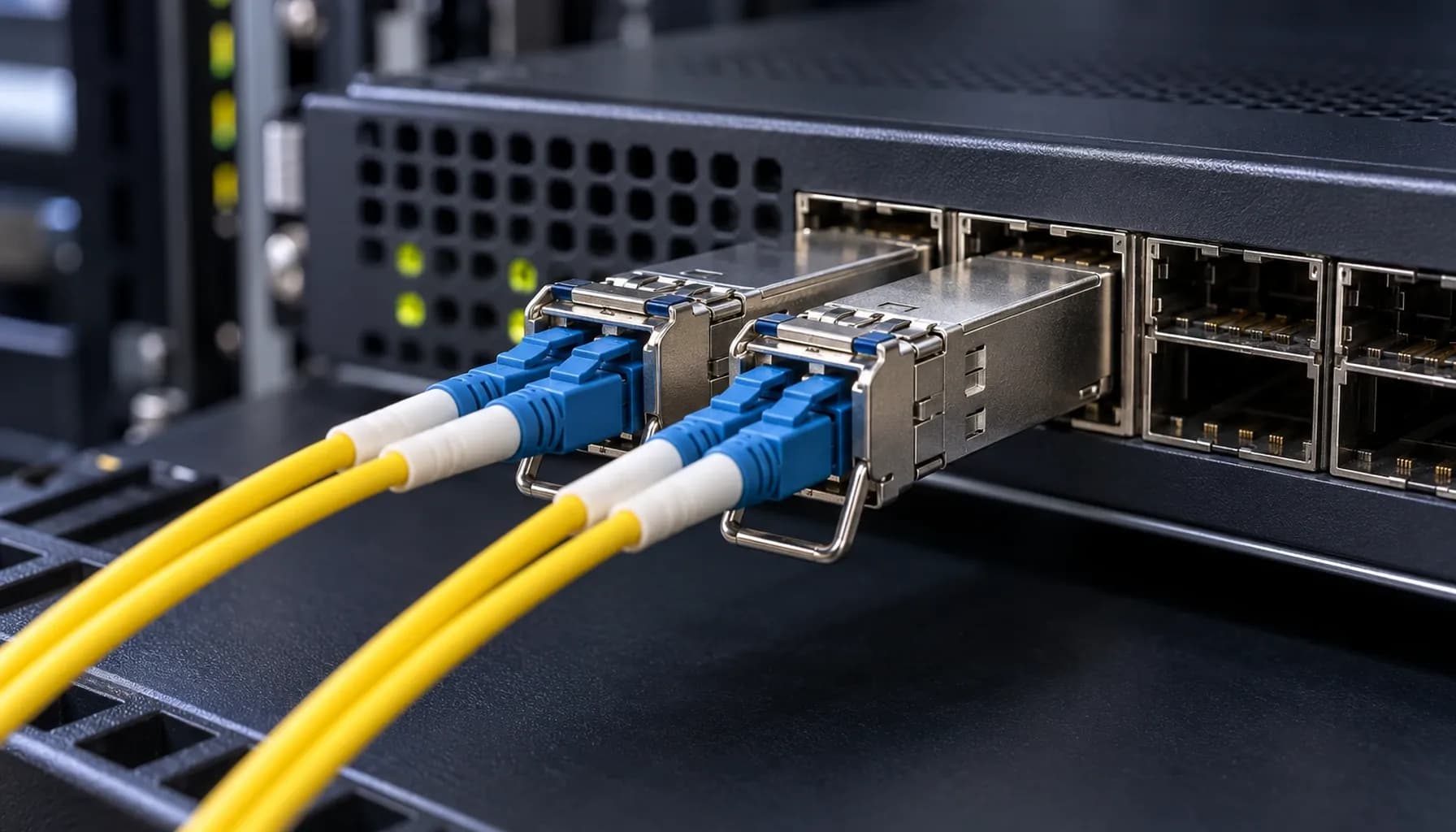
Single-Mode (OS2) vs Multi-Mode (OM3/OM4) Wiring & CLI Verification Cheat-Sheet: Power Budget, OTDR Traces & Vendor Lock Commands for UAE Enterprises
Single-Mode (OS2) vs Multi-Mode (OM3/OM4) Wiring & CLI Verification Cheat-Sheet: Power Budget, OTDR Traces & Vendor Lock Commands for UAE Enterprises In modern UAE enterprise networks, selecting the right fiber optic cabling is crucial for performance, scalability, and cost-efficiency. This article delves into the technical intricacies of Single-Mode OS2 and Multi-Mode OM3/OM4 wiring, providing a comprehensive comparison, power budget analysis, OTDR trace interpretation, and essential CLI commands for Cisco, Arista, and Juniper switches. This guide aims to equip network engineers with the knowledge to make informed decisions and troubleshoot effectively. 1. Single-Mode OS2 vs Multi-Mode OM3/OM4: A Technical Comparison Key Differences in Specifications and Standards When choosing between Single-Mode OS2 and Multi-Mode OM3/OM4, understanding their technical specifications is paramount. The following table provides a detailed comparison: | **Specification** | **Single-Mode OS2** | **Multi-Mode OM3** | **Multi-Mode OM4** | |----------------------------|------------------------------|------------------------------|------------------------------| | **Core Diameter** | 8-10 microns | 50 microns | 50 microns | | **Bandwidth (MHz·km)** | Not applicable | 2000 MHz·km | 4700 MHz·km | | **Distance (10G)** | Up to 10 km | Up to 300 m | Up to 400 m | | **Distance (40G/100G)** | Up to 10 km | Up to 100 m | Up to 150 m | | **Attenuation (dB/km)** | 0.4 dB/km @ 1310 nm | 3.5 dB/km @ 850 nm | 3.5 dB/km @ 850 nm | | **Wavelengths Supported** | 1310 nm, 1550 nm | 850 nm, 1300 nm | 850 nm, 1300 nm | | **Cost per Meter** | Higher | Lower | Lower | | **Common Applications** | Long-haul, high-speed links | Data centers, short-reach | Data centers, short-reach | Key takeaway: Single-Mode OS2 is ideal for long-distance applications due to its lower attenuation and higher bandwidth capacity, while Multi-Mode OM3/OM4 is suitable for short-reach, high-density deployments in data centers. Distance, Loss, and Cost Considerations In UAE enterprise networks, the choice between OS2 and OM3/OM4 often hinges on the required distance and budget constraints. Distance: OS2 can transmit data over much longer distances (up to 10 km) compared to OM3 (up to 300 m) and OM4 (up to 400 m). This makes OS2 the preferred choice for campus networks and metropolitan area networks (MANs). Loss: OS2 exhibits lower attenuation (0.4 dB/km at 1310 nm) compared to OM3/OM4 (3.5 dB/km at 850 nm). This translates to lower signal loss over long distances. Cost: While OS2 cables are more expensive per meter, the overall cost may be justified for long-distance applications. Conversely, OM3/OM4 cables are more cost-effective for short-reach, high-density deployments. For a more detailed analysis of distance, loss, and cost, refer to our previous article: Single-Mode OS2 vs Multi-Mode OM3/OM4: Distance, Loss & Cost for UAE Enterprise Networks . 2. Power Budget Analysis for OS2 and OM3/OM4 Links Understanding Power Budget The power budget is the difference between the transmitter's output power and the receiver's sensitivity. It determines the maximum allowable loss in the fiber link. OS2 Power Budget: Typically, OS2 links have a power budget of around 20 dB for 10G links. This allows for longer distances with minimal signal loss. OM3/OM4 Power Budget: For OM3/OM4, the power budget is typically 2.3 dB for 10G links. This lower budget is due to the higher attenuation at 850 nm. Calculating Power Budget To calculate the power budget, use the following formula: For example, if the transmitter output power is -3 dBm and the receiver sensitivity is -15 dBm, the power budget is: Ensuring Adequate Power Budget When designing fiber links, ensure that the total link loss is within the power budget. The total link loss includes fiber attenuation, connector losses, and splice losses. Key takeaway: Always calculate the power budget to ensure that the fiber link can support the required data rate and distance. 3. OTDR Trace Interpretation for OS2 and OM3/OM4 Links Introduction to OTDR Optical Time-Domain Reflectometer (OTDR) is a crucial tool for testing and troubleshooting fiber optic cables. It measures the return loss and reflection of light pulses to identify faults and measure attenuation. Interpreting OTDR Traces OS2 Traces: OS2 traces typically show a clean, straight line with minimal reflections due to the low attenuation and high bandwidth. Any significant reflections or spikes may indicate a fault or poor connector. OM3/OM4 Traces: OM3/OM4 traces may show more reflections and attenuation due to the higher core diameter and lower bandwidth. However, the overall trace should still be relatively smooth. Common Issues Identified by OTDR Fiber Breaks: A sudden drop in the trace indicates a fiber break. Connector Losses: A spike followed by a drop indicates a connector with high loss. Macro-Bends: A gradual increase in attenuation indicates a macro-bend in the fiber. Key takeaway: Use OTDR traces to identify and locate faults in fiber optic cables, ensuring optimal performance and reliability. 4. Multi-Vendor Switch CLI Configuration Block Cisco, Arista, and Juniper CLI Commands Configuring fiber optic interfaces on multi-vendor switches requires specific commands. Below is a cheat-sheet for Cisco, Arista, and Juniper switches. Cisco Catalyst/Nexus Arista 7050X Juniper QFX Vendor Lock Commands Cisco: Use the transceiver type command to set the appropriate transceiver type. Arista: Use the transceiver type command to set the appropriate transceiver type. Juniper: Use the set interfaces command with the transceiver option to set the appropriate transceiver type. Key takeaway: Use the correct CLI commands to configure fiber optic interfaces on multi-vendor switches, ensuring compatibility and optimal performance. 5. Conclusion and Recommendations Final Recommendations Choose OS2 for Long-Distance Applications: If your network requires long-distance connectivity (e.g., between buildings or campuses), opt for Single-Mode OS2 cables. Use OM3/OM4 for Data Centers: For high-density, short-reach deployments in data centers, Multi-Mode OM3/OM4 cables are more cost-effective and efficient. Perform Power Budget Analysis: Always calculate the power budget to ensure that the fiber link can support the required data rate and distance. Utilize OTDR for Troubleshooting: Use OTDR traces to identify and locate faults in fiber optic cables, ensuring optimal performance and reliability. Configure Correct Transceiver Types: Ensure that the correct transceiver types are configured on multi-vendor switches using the appropriate CLI commands. Additional Resources For more detailed information on fiber optic infrastructure hardware, refer to our comprehensive comparison: Strinex vs FS.com vs Alphabridge: Side-by-Side Single-Mode (OS2) vs Multi-Mode (OM3/OM4) Infrastructure Hardware Comparison . Key takeaway: Selecting the right fiber optic cabling and configuring it correctly is crucial for network performance, reliability, and cost-efficiency. By following this guide, UAE enterprises can make informed decisions about their fiber optic cabling and ensure that their networks are optimized for performance and scalability.
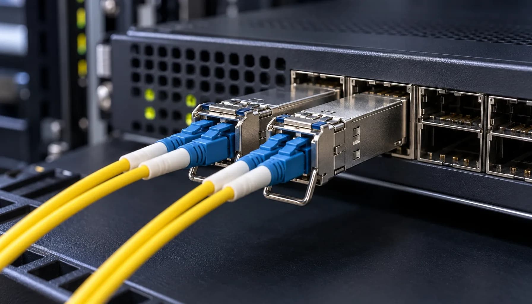
Strinex vs FS.com vs Alphabridge: Side-by-Side Single-Mode (OS2) vs Multi-Mode (OM3/OM4) Infrastructure Hardware Comparison
Strinex vs FS.com vs Alphabridge: Side-by-Side Single-Mode (OS2) vs Multi-Mode (OM3/OM4) Infrastructure Hardware Comparison Introduction: Choosing the Right Fiber Infrastructure for Modern Networks In today's data center and enterprise environments, selecting the appropriate fiber infrastructure is critical for performance, scalability, and cost-effectiveness. The choice between single-mode (OS2) and multi-mode (OM3/OM4) fiber often dictates the network's capabilities and future-proofing. This article provides a detailed comparison of infrastructure hardware from Strinex, FS.com, and Alphabridge, focusing on real-world deployment scenarios with Cisco Catalyst/Nexus, Arista 7050X, and Juniper QFX switches. 1. Distance and Loss: Single-Mode OS2 vs Multi-Mode OM3/OM4 Single-Mode OS2: Long Haul and Low Loss Single-mode OS2 fiber is designed for long-distance transmission with minimal loss. It supports distances up to 10 km and even beyond, depending on the transceiver type and power budget. The typical attenuation for OS2 fiber is around 0.4 dB/km at 1310 nm and 0.25 dB/km at 1550 nm. Advantages: Long Distance Support: Ideal for campus networks, metropolitan area networks (MANs), and inter-data center links. Lower Attenuation: Less signal loss over long distances compared to multi-mode fiber. Higher Bandwidth: Supports higher data rates without significant degradation. Disadvantages: Higher Cost: OS2 transceivers and infrastructure are generally more expensive. Complex Installation: Requires precise alignment and more expensive connectors. Multi-Mode OM3/OM4: Short to Medium Range Multi-mode OM3 and OM4 fibers are optimized for shorter distances, typically up to 300 meters for OM3 and 550 meters for OM4 at 10 Gbps. The attenuation for OM3 is around 3 dB/km at 850 nm, while OM4 has an attenuation of approximately 2.3 dB/km at the same wavelength. Advantages: Cost-Effective: Lower cost for transceivers and infrastructure. Ease of Installation: More forgiving in terms of alignment and connector quality. Sufficient for Most Enterprise Needs: Adequate for data centers and enterprise LANs. Disadvantages: Shorter Distance Support: Limited to shorter spans compared to single-mode. Higher Attenuation: More signal loss over distance. Comparative Table: Distance and Loss | Specification | Single-Mode OS2 | Multi-Mode OM3 | Multi-Mode OM4 | |---------------------|-----------------|----------------|-----------------| | **Distance (10 Gbps)** | Up to 10 km | Up to 300 m | Up to 550 m | | **Attenuation (dB/km)** | 0.4 @ 1310 nm | 3.0 @ 850 nm | 2.3 @ 850 nm | | **Bandwidth (MHz·km)** | N/A | 2000 | 4700 | | **Typical Application** | Long-haul, MAN | Data centers, LANs | Data centers, LANs | Key takeaway: Single-mode OS2 is best for long-distance, high-bandwidth applications, while multi-mode OM3/OM4 is suitable for shorter distances and cost-sensitive environments. 2. Cost Comparison: Infrastructure and Transceivers Single-Mode OS2: Higher Initial Costs The initial investment for single-mode OS2 infrastructure is higher due to the cost of fiber, connectors, and transceivers. For instance, a typical OS2 SFP+ transceiver can cost between $50 to $100, whereas a multi-mode OM4 SFP+ transceiver may cost around $20 to $50. Multi-Mode OM3/OM4: Economical for Short to Medium Ranges Multi-mode OM3/OM4 infrastructure offers a more economical solution for short to medium range applications. The cost of fiber and connectors is lower, and transceivers are generally less expensive. However, the cost savings can be offset by the need for more frequent repeaters or additional access points in larger networks. Cost Comparison Table | Component | Single-Mode OS2 | Multi-Mode OM3 | Multi-Mode OM4 | |----------------------|-----------------|----------------|-----------------| | **Fiber Cost per Meter** | $0.50 | $0.30 | $0.35 | | **Connector Cost per Pair** | $5.00 | $3.00 | $3.50 | | **SFP+ Transceiver Cost** | $70 | $30 | $40 | | **Total Cost for 1 km Link (10 Gbps)** | $1,200 | $600 | $700 | Key takeaway: While single-mode OS2 has higher upfront costs, it may be more cost-effective for long-distance applications due to fewer repeaters and less signal loss. 3. Multi-Vendor Switch Compatibility and CLI Configuration Cisco, Arista, and Juniper Compatibility All three vendors—Cisco, Arista, and Juniper—support both single-mode OS2 and multi-mode OM3/OM4 transceivers. However, it is crucial to ensure that the transceivers are compatible with the specific switch model and firmware version. Cisco Configuration Example Arista Configuration Example Juniper Configuration Example Key takeaway: Ensure transceiver compatibility with the switch model and firmware version. Use the correct CLI commands to configure the interface for single-mode or multi-mode operation. 4. Standards and Compliance Industry Standards Both single-mode OS2 and multi-mode OM3/OM4 fibers adhere to industry standards such as ITU-T G.652 for OS2 and ISO/IEC 11801 for OM3/OM4. These standards ensure interoperability and performance across different vendors and applications. Compliance and Testing OS2 Compliance: Requires compliance with ITU-T G.652 standards, ensuring low dispersion and attenuation. OM3/OM4 Compliance: Requires compliance with ISO/IEC 11801 standards, ensuring high bandwidth and low attenuation at 850 nm. Testing and Certification Proper testing and certification are essential for ensuring the performance and reliability of the fiber infrastructure. Tools such as OTDR (Optical Time-Domain Reflectometer) and light source and power meter are commonly used for testing. Key takeaway: Adherence to industry standards and proper testing are critical for ensuring the performance and reliability of the fiber infrastructure. Conclusion: Making the Right Choice for Your Network Selecting between single-mode OS2 and multi-mode OM3/OM4 fiber depends on the specific needs of your network, including distance, bandwidth, and cost considerations. Single-mode OS2 is ideal for long-distance, high-bandwidth applications, while multi-mode OM3/OM4 offers a cost-effective solution for shorter distances. Final Recommendations For Long-Distance, High-Bandwidth Needs: Choose single-mode OS2. For Cost-Effective, Short to Medium Range Applications: Choose multi-mode OM3/OM4. By understanding the differences in distance, loss, cost, and compatibility, you can make an informed decision that aligns with your network requirements and budget. Key takeaway: The choice between single-mode OS2 and multi-mode OM3/OM4 should be based on a comprehensive analysis of your network's specific needs, including distance, bandwidth, and cost. --- This article provides a detailed comparison of single-mode OS2 and multi-mode OM3/OM4 fiber infrastructure, offering actionable insights for network engineers and decision-makers. For more in-depth information on related topics, check out our other articles: Single-Mode OS2 vs Multi-Mode OM3/OM4: Distance, Loss & Cost for UAE Enterprise Networks Third-Party SFP Module Coding & EEPROM Programming: The Complete UAE Enterprise Network Guide (2026) 100G QSFP28 Optical Form Factors: SR4 vs LR4 vs CWDM4 vs PSM4 Compared: The Complete UAE Enterprise Procurement Guide (2026) BiDi SFP+ Transceivers: Doubling Fiber Capacity over Single Strand (WDM Simplex): The Complete UAE Engineering Guide (2026)
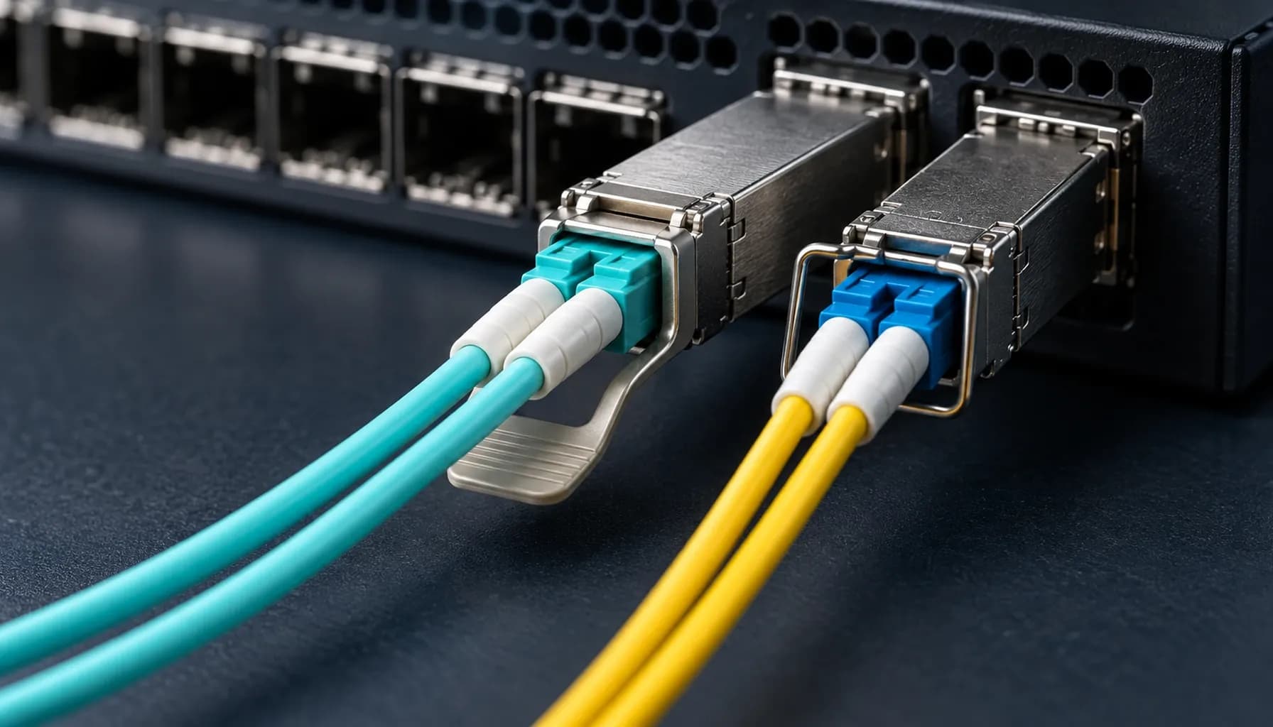
Single-Mode OS2 vs Multi-Mode OM3/OM4: Distance, Loss & Cost for UAE Enterprise Networks
Dubai Internet City data centres and Abu Dhabi industrial SCADA estates expose the same mistake in different forms: teams choose fibre by cable price, then discover that optics or the route makes the decision expensive. Start with the installed plant, the longest permanent link, and the optical budget. OS2 is the default for new campus, metro, and building-to-building routes in the UAE. OM3 and OM4 still make sense in contained equipment rooms with short, predictable 850 nm links. They are different transmission systems with different failure modes and cost curves. Operating principles, reach and loss budget OS2 single-mode fibre has an approximately 9 µm core and normally carries 1310 nm or 1550 nm optics. Its low attenuation and lack of modal dispersion make it the rational choice beyond the data-hall boundary. OM3 and OM4 use a 50 µm core and 850 nm VCSEL optics, where modal bandwidth sets practical reach. Use 300 m for OM3 and 400 m for OM4, subject to the installed channel class and vendor data sheet. A 10GBASE-LR optic is specified for 10 km over OS2. Build the budget before ordering optics: $P_{\text{budget}} = P_{\text{Tx\_min}} - S_{\text{Rx\_sens}}$. Deduct fibre attenuation, connector pairs, splices, and a margin for dirt, ageing, and the next patch panel. For a new OS2 backbone, pair the route with a compatible Strinex 10G/25G optical transceiver only after confirming wavelength, reach, connector type, and host coding. Comparison matrix | Parameter | Strinex Alpha Bridge | FS.com Equivalent | Cisco OEM | Generic / Refurbished | | :--- | :--- | :--- | :--- | :--- | | OS2 long-reach option | Verify LR or 20 km SKU, 1310 nm | Select exact LR/ER variant | Qualified LR optic | Validate label and test report | | OM3/OM4 short-reach option | Verify SR SKU, 850 nm | Select exact SR variant | Qualified SR optic | Confirm actual wavelength | | Host coding | Confirm Cisco, Juniper, Arista or MikroTik target | Order coded variant | Native coding | Often unknown or locked | | DDM telemetry | Check SFF-8472 support | Check module data sheet | Platform dependent | Frequently inconsistent | | UAE supply and warranty | Local stock and support | Confirm lead time and return path | Confirm channel stock | Verify provenance and warranty | A brand name does not repair a mismatched wavelength or an exhausted loss budget. Cisco OEM can be a conservative procurement path, but it does not remove the need to validate DOM readings, fibre type, and the switch release in use. Interoperability and host validation Cisco, Juniper, Arista, and MikroTik ports need matching speed, wavelength, connector, and fibre mode at both ends. Verify SFF-8431 host interface and SFF-8472 diagnostic support before treating a module as interchangeable. Cisco and Juniper platforms may enforce vendor EEPROM checks; a permissive port is not proof of a healthy link. Record the host model, release, optic part and serial number, DDM thresholds, and measured receive power during staging. For coding constraints and EEPROM checks, see Third-Party SFP Module Coding & EEPROM Programming . Use the SFF-8472 DOM/DDM diagnostics field guide to interpret telemetry against the module data sheet. Field deployment and maintenance Treat bend radius as an optical requirement. Hold a minimum installed bend radius above $30\text{ mm}$ for patch leads unless the manufacturer specifies a larger limit. Inspect every ferrule before mating and follow IEC 61300-3-35: dry clean first, use wet-to-dry cleaning when contamination persists, inspect again, and cap exposed connectors. Recommended diagnostic utilities and testing tools Fluke Networks FiberInspector Pro checks ferrule end faces before a connector consumes the link budget. EXFO MaxTester OTDR locates splice, connector, and bend events on OS2 routes. VIAVI SmartClass Fiber OLP-88 measures end-to-end insertion loss and optical power for acceptance testing. Frequently asked questions Should a new UAE campus backbone use OS2? Yes, unless the route is permanently confined to short data-hall links with a clear OM3 or OM4 standard. OS2 preserves options for 10 km LR optics and later capacity changes without replacing the cable plant. Specify the optic reach for the actual route and retain usable margin. Is OM4 always better than OM3? OM4 offers more effective modal bandwidth and a longer 10GBASE-SR channel than OM3. It does not turn 850 nm multimode into a campus technology or compensate for dirty connectors. Use it where the extra reach or high-speed roadmap has documented value. Can a Cisco switch use a third-party optic? Many Cisco models can, subject to platform policy, release, coding, and support rules. Stage the exact optic in the intended port and confirm link, DOM, alarms, and error counters. Keep an approved spare with identical coding, not merely the same wavelength. How much loss margin should a fibre design retain? Calculate every fixed loss first, then reserve a practical margin for contamination, ageing, and future cross-connects. The exact allowance depends on the optic specification and maintenance regime. A design that only passes on paper will fail first during a dusty maintenance window. Why does a link fail after an apparently clean installation? Most short fibre faults come from contaminated ferrules, reversed polarity, tight bends, or incompatible optics. Inspect both ends and compare transmit and receive power with the module data sheet. If those checks pass, use insertion-loss testing or OTDR traces to isolate the event. UAE selection checklist Choose OS2 for backbone, campus, and inter-building routes; use OM3 or OM4 for short controlled data-centre channels. Calculate the optical budget and deduct every connector, splice, fibre kilometre, and engineering margin. Validate optic, host coding, firmware, DOM thresholds, and receive power before dispatch. Keep patch-lead bends above $30\text{ mm}$ and follow IEC 61300-3-35 cleaning practice. Conclusion and local UAE procurement OS2 is the sensible long-life cable plant for UAE backbone work; OM3 and OM4 earn their place in short, dense equipment-room links. Strinex holds local Dubai stock for selected optical modules and can support same-day dispatch where stock and order cut-off permit. Review the live 10G/25G optical transceiver range and match the module to the tested host and measured fibre channel.