
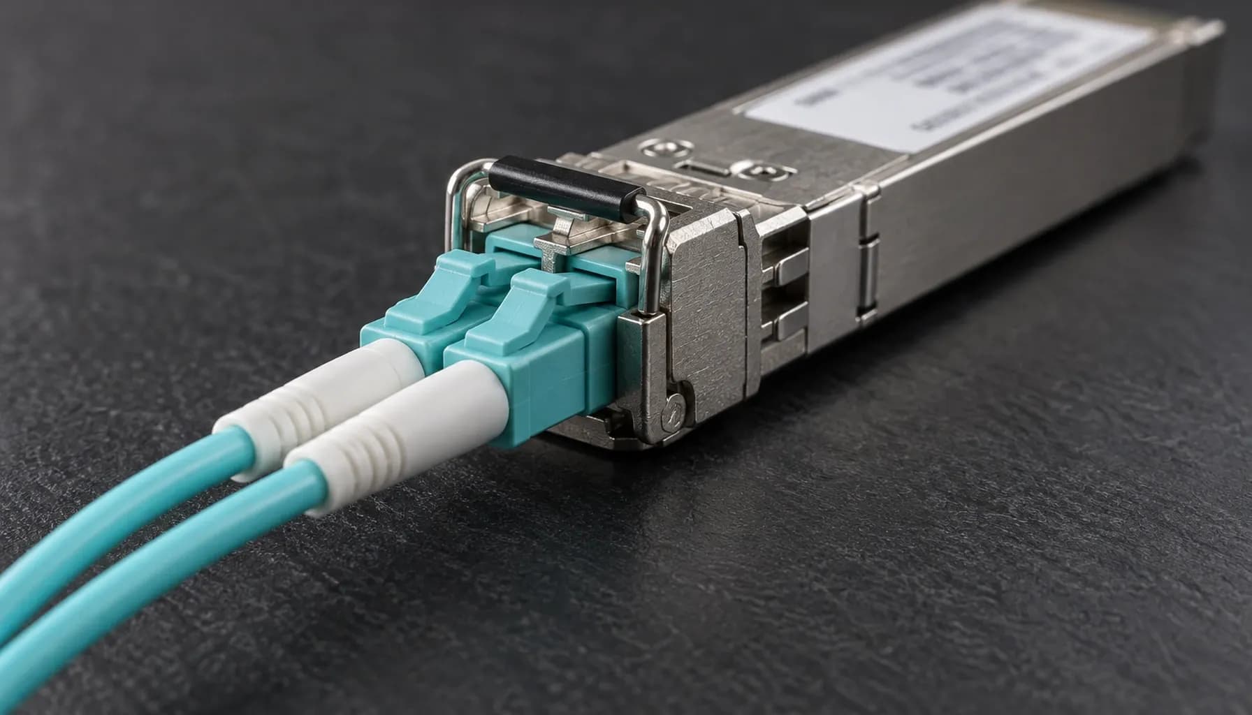
100G CRC counters are routinely misclassified as proof of a defective switch ASIC. In UAE high-density deployments, heat, dust, connector contamination, marginal optics, bend stress, EMI, lane imbalance, and unqualified transceivers are more likely causes. Neither “stomped CRC” nor “invalid CRC” identifies where corruption occurred. Both are ingress symptoms; isolation must correlate MAC, FEC, PMD/PCS, DOM, and link-state evidence.
CRC Architecture at 100G: What the Counters Actually Mean
FCS, FEC, and lane integrity
At 100G, Ethernet still uses IEEE 802.3’s CRC-32 frame check sequence (FCS); FCS is not FEC, BER, or a PCS symbol counter. SR4 and ER4 carry frames over four 25G lanes, DR1 over one 100G PAM4 lane, and FR1/LR1 over two 50G PAM4 lanes. FEC can repair physical errors before MAC validation; uncorrectable damage can cause loss, malformed frames, or link faults. CR4 uses four electrical lanes over qualified DAC/ACC.
Match the PHY before comparing counters. The 100GBASE PHY Family Decoded: SR4, DR1, FR1, LR1 and ER4 by Lane Architecture, Media and Reach (2026) reference provides the correct media baseline.
What “stomped” does—and does not—mean
Invalid CRC means the calculated FCS differs from the received FCS. On Nexus 9000 and other Cisco ASIC telemetry, stomped CRC typically counts bad-FCS frames that ingress hardware rejected or marked; the ASIC may be the detector, not the corruption source. Coverage varies by ASIC and release, and platforms may label the same event as CRC, bad CRC, or ingress discard. It is not an IEEE fault class. Connectors, optics, fiber, EMI, endpoint-generated frames, and internal port faults can all produce it.
Key takeaway: “Stomped CRC” describes hardware handling of a bad-FCS frame, not the origin of corruption. It is evidence to investigate, never an ASIC diagnosis.
High-Density CRC and Physical-Layer Comparison
Use this evidence matrix before replacing hardware; no single counter establishes root cause.
| Observable | Layer or standard | Meaning or metric | Strong correlation | Leading suspects | Decisive test |
|---|---|---|---|---|---|
| Invalid CRC | IEEE 802.3 MAC/FCS | Calculated CRC-32 differs from received FCS | Port, frame size, traffic | Endpoint, media, optic, PHY/MAC, ASIC | Connect independently qualified media |
| Stomped CRC | Vendor ASIC ingress counter; not IEEE | Bad-FCS frame blocked; label varies by release | Equivalent CRC and ingress-drop counters | Same causes as invalid CRC | Repeat on a known-good port |
| FEC corrected | 100GBASE PHY FEC | Correctable physical codewords | Receive power, temperature, EMI, lane | Marginal optic, fiber, connector | Swap the optic |
| FEC uncorrectable | 100GBASE PHY FEC | Unrecoverable blocks or symbols | Lane loss, low receive power | Optic, connector, PCS | Inspect, clean, and swap |
| LOS or remote fault | PMD and link manager | Link unavailable or remote-side failure | Flaps, temperature, power | Optic, fiber, transceiver | Approved loop or known-good port |
| PCS/SERDES errors | PCS and PMD | Symbol, coding, or alignment errors | Specific lane or module | Optic, cable, SerDes | Move the complete module |
| Parity, ECC, or internal drops | Switch data path | Internal integrity or resource failure | Ports sharing an ASIC | ASIC, buffer, line card | Two media sets on the same port |
Cable and connector evidence
A fiber or connector does not need to be visibly broken to fail. Dust, ferrules, contamination, and bend violations can create intermittent lane errors while average DOM readings remain acceptable. Inspect every mating surface with a calibrated scope and clean with approved tools. On CR4 links, verify bend radius and DAC/ACC vendor qualification.
Field Isolation Workflow
Capture a controlled baseline
Label and photograph the path. Capture baseline and counter deltas over a fixed interval under representative traffic; do not clear counters first. Record CRC/stomp, input errors, FEC corrected and uncorrectable, PCS or symbol errors, DOM, temperature, flaps, and internal parity/ECC counters. Confirm media type, lane architecture, reach, firmware, and vendor support. Apply the checks in Pre-Ship Optics Acceptance for 100G Ports: Module-Type, DOM Threshold and Reach Checks (2026).
Inspect the physical layer
Use a calibrated inspection scope. Contamination, ferrule damage, bend violations, dirty bulkheads, and EMI are more common than spontaneous fiber failure. Clean with approved tools and never look into a fiber. Healthy DOM does not exclude burst errors or a marginal lane.
Use controlled substitutions
Test the suspect port with an independently qualified optic and cable, then place the suspect media on a known-good port. If the fault follows the media, that port is not the root cause. If it disappears with clean media, the original path is implicated. If one port fails with two qualified media sets, escalate its PHY, cage, or line card. Moving the link to another line card separates the suspect port from its original ASIC. Never cross-connect fibers outside an approved procedure.
Assign cause from correlation
One impaired lane, rising FEC, variable or low receive power, and temperature sensitivity point toward optics or connectivity. Identical failures with clean media, multiple ports on one ASIC, internal parity/ECC events, or load-dependent pipeline drops point toward switch hardware or software. Reproduce unicast, multicast, ECMP, VLAN rewrite, oversize, and QoS cases only under change control; load-only failures suggest pipeline behavior but do not alone prove an ASIC fault.
Key takeaway: A defensible ASIC case requires persistence on the same port or shared ASIC with qualified media plus corroborating internal evidence. Persistence alone is not causation.
Multi-Vendor CLI Evidence Collection
Collect read-only evidence first. Command wording changes by platform and release; use ? to confirm support.
1# Cisco Nexus 9000 / NX-OS2show interface Ethernet 1/1 counters3show interface Ethernet 1/1 counters errors4show interface Ethernet 1/1 transceiver dom5show interface Ethernet 1/1 transceiver detail6
7# Cisco Catalyst 9500 / IOS XE8show interfaces Ethernet1/1 counters errors9show interfaces transceiver detail10show interfaces status11
12# Arista 7050X3 / EOS13show interfaces counters errors14show interfaces Ethernet1 counters15show interfaces Ethernet1 transceiver dom16show interfaces Ethernet1 transceiver detail17
18# Juniper QFX5120 / Junos19show interfaces diagnostics20show interfaces diagnostics optics21show interfaces et-0/0/0 extensive | match "CRC|error|drop"
Archive the same observation window for each platform. NX-OS and IOS XE counter labels are not interchangeable; EOS may expose generic interface errors plus PHY diagnostics; Junos often separates interface, optic, and chassis data. Avoid clear counters until the initial snapshot is complete.
Platform and Migration Considerations
Cisco Catalyst 9500/9600 IOS XE and Nexus 9000 NX-OS expose CRC and transceiver diagnostics, but CRC and stomped semantics remain ASIC- and release-specific. Arista 7050X3 EOS generally reports interface errors and optical diagnostics rather than Cisco terminology; Juniper QFX5120 Junos separates interface, optic, and chassis diagnostics. Confirm supported optics and releases: a QSFP28 shell proves neither reach nor PHY compatibility.
In data center high-speed migration (10g -> 25g -> 100g) troubleshooting diagnostics, use the Data Center High-Speed Migration (10G -> 25G -> 100G): Comprehensive Engineering & Architecture Guide: The Complete UAE Engineering Guide (2026) for staged, module- and lane-aware acceptance.
Frequently Asked Questions
Does “stomped CRC” prove that the switch ASIC is faulty?
No. “Stomped CRC” is a platform-specific count of bad-FCS frames blocked at hardware ingress, not an IEEE category or corruption location. Connectors, optics, fiber, EMI, and endpoint faults can produce it. Diagnose an ASIC only after controlled substitutions reproduce the fault on one port with qualified media and internal evidence corroborate it.
Is invalid CRC always a cable problem?
No. It states only that received FCS differs from calculated FCS. Causes include endpoint frames, optics, fiber, connectors, PMD/PCS, MAC/PHY, and rarely switch logic. Correlate CRC deltas with FEC, DOM, lane errors, flaps, and substitution results. The CRC counter alone cannot assign physical versus internal root cause.
Why can 100G show FEC errors without CRC errors?
At 100G, FEC can repair a physical codeword before the MAC sees it. Corrected blocks increment a FEC counter without creating an invalid Ethernet FCS. Beyond correction capacity, blocks may be dropped or malformed frames may reach the MAC, causing CRC errors, loss, or link faults. Rising corrected FEC is an earlier warning than CRC.
Should I clean and retest every connector?
Record DOM, FEC, CRC, temperature, and power before disturbing the link. Inspect with a calibrated scope, clean correctly, and retest under the same traffic and duration. If the fault follows media to a clean port, external media is implicated. If it remains on one port with two qualified media sets, escalate that port/PHY or line card.
When is an ASIC or line-card RMA justified?
Require the fault to persist on one port or line card with independently qualified optics, cables, connectors, and firmware while the same media works on a healthy port. Corroborate with internal parity/ECC, buffer, or ingress-drop counters. Multiple failing ports on one ASIC strengthen the case; one CRC counter alone does not justify an RMA.
Key Takeaways
- Preserve CRC, FEC, DOM, temperature, and link-history baselines before swapping or clearing counters.
- Treat stomped and invalid CRC as symptoms, not component diagnoses.
- Verify PHY type, lane architecture, reach, DOM limits, firmware, and support.
- Use suspect-port and known-good-port substitutions before escalation.
- Require internal parity/ECC or shared-ASIC evidence before an ASIC RMA.
Conclusion
Keep media, PHY, and switch-data-path evidence separate to make 100G faults tractable. Apply these acceptance gates during 10g-to-25g-to-100g migration, then specify compatible optics, DAC/ACC, and support in the Strinex catalogue.