
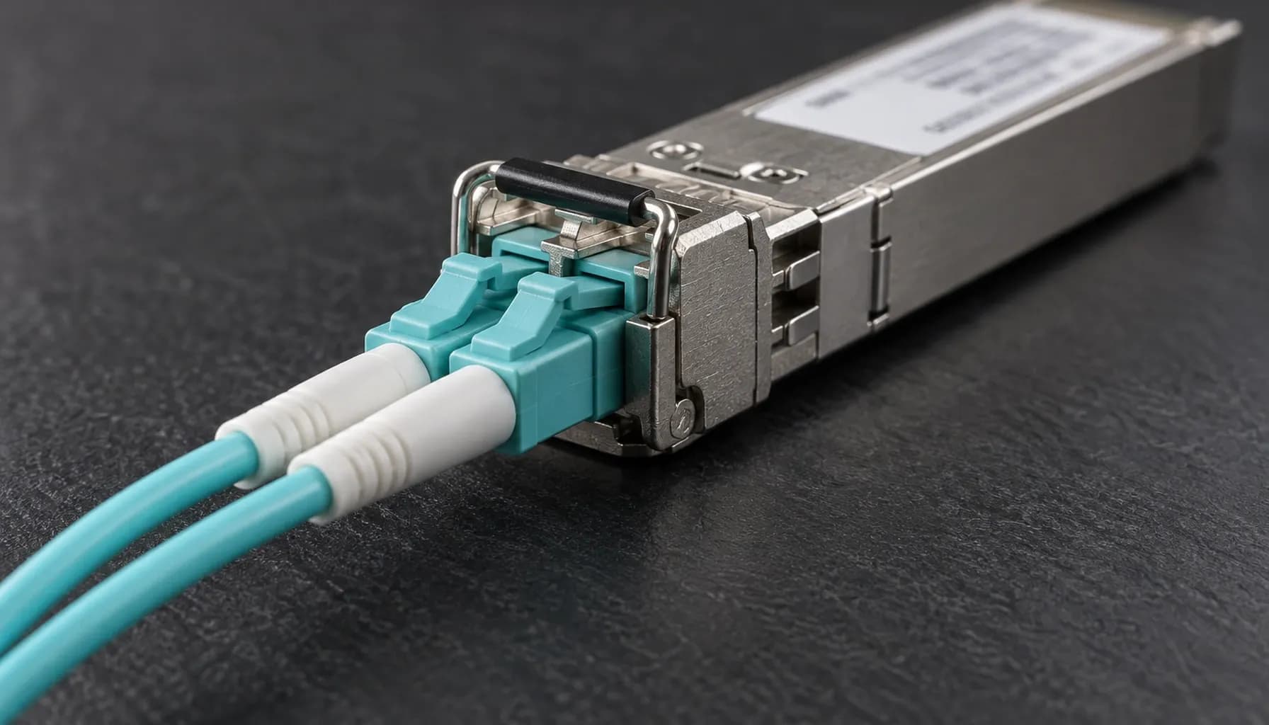
The 100G Migration Decision: Lane Architecture Is the First Design Constraint
A 100Gb/s uplink is not one optical technology. It is a family of implementations with materially different lane counts, fibre types, laser designs, reach, power budgets, and transceiver requirements. In a data center high-speed migration (10g -> 25g -> 100g), the practical choice is rarely “100G versus non-100G”; it is whether the target fabric requires multimode or single-mode connectivity, four parallel lanes or one high-speed lane, and short rack-room reach or a 10–40 km campus/building span.
SR4, DR1, FR1, LR1 and ER4 therefore must be evaluated as an architecture rather than as interchangeable QSFP28 labels. The distinction becomes operationally important when deploying across Cisco Catalyst and Nexus platforms, Arista 7050X switches, and Juniper QFX systems, where optics validation, interface breakout behaviour, and transceiver diagnostics can differ by platform and software release.
The broader migration context is covered in the Data Center High-Speed Migration (10G -> 25g -> 100G): Comprehensive Engineering & Architecture Guide: The Complete UAE Engineering Guide (2026).
PHY Family Comparison: Specifications That Change the Design
The following table compares the principal members of the 100GBASE PHY family. “Lane” refers to the high-speed optical lanes presented by the module; it does not necessarily mean that every implementation uses identical electrical signalling.
| PHY | IEEE reference | Optical architecture | Media | Typical reach | Fibre and connector implication |
|---|---|---|---|---|---|
| 100GBASE-SR4 | IEEE 802.3bm | 4 × 25Gb/s, 850 nm VCSEL, NRZ | OM3/OM4 multimode | Up to 100 m | Four parallel optical paths; commonly used for short data-center links |
| 100GBASE-DR1 | IEEE 802.3cu family | 1 × 100Gb/s, 1310 nm, PAM4 | OM4 multimode or single-mode variants | 500 m MMF; SMF options may reach 10 km | One high-speed lane; avoids four-lane parallel optics |
| 100GBASE-FR1 | IEEE 802.3cu | 1 × 100Gb/s, 1310 nm, PAM4 | Single-mode fibre | 2 km | Low-cost single-mode option for building or campus aggregation |
| 100GBASE-LR1 | IEEE 802.3cu | 1 × 100Gb/s, 1310 nm, PAM4 | Single-mode fibre | 10 km | Single-lane reach for longer intra-campus or metropolitan links |
| 100GBASE-ER4 | IEEE 802.3ba | 4 × 25Gb/s, 1310 nm wavelength set, NRZ | Single-mode fibre | 40 km | Four wavelengths over one duplex fibre pair; larger optical budget |
Key takeaway: SR4 is a parallel multimode architecture; DR1, FR1 and LR1 are single-lane 1310 nm single-mode-oriented designs; ER4 is a four-wavelength single-mode architecture. The PHY label must be matched to the actual fibre path, not selected from reach alone.
SR4: Low Latency Inside the Data Center
SR4 uses four 25Gb/s lanes, normally at 850 nm over OM3 or OM4 multimode fibre. Its principal advantage is maturity and broad availability of 100G QSFP28 modules. The trade-off is the requirement for four optical lanes and the need to maintain multimode fibre quality, connector cleanliness, and bend radius.
SR4 is appropriate for short server-to-switch or switch-to-switch connections where both ends are inside the same data hall or closely controlled row. It is less attractive for a long campus route because multimode is generally unavailable beyond the optical budget, and fibre transitions add engineering risk. In a migration from 10G or 25G, SR4 can provide a straightforward QSFP28 endpoint while retaining a familiar fibre infrastructure.
DR1, FR1 and LR1: The Single-Lane 100G Choices
The single-lane family uses 100Gb/s PAM4 at approximately 1310 nm. PAM4 doubles the signalling rate relative to NRZ, improving spectral efficiency and allowing a single optical lane to carry the full 100G payload. The associated transceiver and electronics are more demanding than 25G NRZ, but the fibre path becomes simpler than a four-lane SR4 or ER4 deployment.
FR1 is the usual starting point for 2 km single-mode links. LR1 extends the same broad architecture to 10 km. DR1 is primarily associated with 500 m multimode connectivity and may also be specified in single-mode variants; procurement should therefore confirm the exact cable and module variant rather than relying on the PHY name.
Key takeaway: For new single-mode infrastructure, FR1 at 2 km or LR1 at 10 km usually provides a cleaner path than SR4. Confirm whether the design requires multimode compatibility before standardising DR1.
ER4: Four Wavelengths for Long-Reach Single Mode
ER4 carries 100Gb/s across four 25Gb/s wavelengths over a duplex single-mode pair, with an optical reach of approximately 40 km. It is not simply “four SR4 lanes”: the wavelengths are combined and separated through wavelength-division multiplexing components, and the module presents one duplex optical interface.
ER4 is relevant when a 40 km route is required but a 400G or newer single-lane ecosystem is not yet justified. Its disadvantages include a more complex and generally more expensive optical assembly, and the need to ensure that the complete path—including patch panels, connectors, splices and any intermediate optical devices—meets the module’s link budget.
How the PHY Choice Affects Switch Interoperability
The switch model alone does not guarantee interoperability. The combination of ASIC, port type, breakout configuration, firmware, optics vendor, and software release determines whether a QSFP28 module will train correctly. Cisco Nexus 9000 and Catalyst 9500 platforms may expose 100G ports directly or through breakout-capable ports, while Arista 7050X implementations may use QSFP28 interfaces with configuration constraints. Juniper QFX platforms also vary by line card and software train.
A conservative migration process is:
- Verify the exact port hardware and supported optic matrix.
- Confirm that the transceiver is supported, or explicitly permit a qualified third-party optic.
- Match the optic to the cable type and measured reach.
- Validate the link with the intended media, temperature and firmware combination.
- Record diagnostics and failure signatures before rolling the change to production.
Illustrative Multi-Vendor Validation Block
The following commands are representative validation steps, not universal deployment recipes. Command syntax must be adapted to the specific platform, line card and release.
1! Cisco Catalyst 9500 / Nexus 90002show version3show inventory4show interfaces transceiver5show interfaces status6configure terminal7 interface Ethernet1/18  description 100G-to-100G SR4 uplink9  speed 100g10  no shutdown11 end12copy running-config startup-config13
14! Arista EOS on 7050X15show version16show inventory17show interfaces transceiver18configure terminal19interface Ethernet120   description 100G-to-100G uplink21   speed 100gfull22   no shutdown23end24write memory25
26! Juniper Junos on QFX27show version28show chassis hardware29show interfaces transceiver extensive30configure31set interfaces et-0/0/0 description 100G-to-100G uplink32set interfaces et-0/0/0 speed 100g33commit and-quit
On Nexus devices, the exact interface naming and breakout commands differ between Ethernet and Ethernet1/1 forms. On Arista, speed 100gfull is normally applied to a dedicated 100G interface; attempting to use it on a breakout member may be rejected. Juniper port names are line-card dependent, and some platforms require an explicit interface-mode or transceiver configuration. Always inspect the platform command reference and supported optic list before configuring.
Key takeaway: Treat transceiver interoperability as a tested interface contract. A module may be electrically compatible yet unsupported by the switch image, breakout configuration, or optic-management policy.
Deployment Guidance for UAE Data Centers
When to Choose SR4
Choose SR4 when the link is short, the existing infrastructure is OM3/OM4, and the operational objective is a low-complexity 100G upgrade using mature QSFP28 hardware. Validate connector cleanliness and ensure that the fibre route does not introduce undocumented patch-panel or bend-radius losses.
When to Choose FR1 or LR1
Choose FR1 for 2 km single-mode routes and LR1 for 10 km routes. These options are generally preferable for data-hall-to-data-hall, building-to-building, or campus aggregation where the organisation wants a single optical lane and a clear path toward higher-speed single-lane designs.
The 1310 nm window is also operationally useful because many single-mode systems already operate in that window. Nevertheless, the transceiver’s specified launch power, receiver sensitivity and link budget remain decisive. Do not infer compatibility from wavelength alone.
When to Choose ER4
Choose ER4 only where the route genuinely approaches 40 km or where the design requires the four-wavelength optical model. For shorter distances, ER4 may add unnecessary cost and complexity. Its physical reach is also not equivalent to guaranteed service distance: every splice, connector, patch lead and optical amplifier changes the engineering margin.
Migration and Power Considerations
A 10G-to-25G-to-100G programme should not treat optics as the final step. Port density, switch backplane capacity, queueing behaviour, buffer requirements, telemetry, and thermal load can determine whether the migration succeeds. High-density 100G ports can also affect power and cooling in Dubai or Abu Dhabi installations, especially where the design uses fanless equipment or restricted airflow.
The power implications of adjacent infrastructure should be assessed alongside the migration. For example, legacy PoE platforms may require an explicit IEEE 802.3bt enablement procedure, including the power-cycle behaviour described in the Enabling IEEE 802.3bt Mode on a Legacy PoE Switch: hw-module switch upoe-plus, the Power-Cycle It Triggers and How to Revert Safely (2026) guide. If a 100G migration is bundled with a PoE refresh, the PSE budget should be modelled rather than estimated; the Cost per 90W Port: PSE Chassis, Expansion Modules and the 15–20% Budget Headroom You Are Paying For (2026) analysis explains the required headroom.
Frequently Asked Questions
Is SR4 compatible with single-mode fibre?
No. SR4 is designed for multimode fibre, principally OM3 or OM4, because its 850 nm VCSEL output and four-lane optical architecture depend on the fibre’s modal characteristics. Using it over single-mode may produce insufficient received power or unstable operation. For single-mode routes, specify an appropriate FR1, LR1, DR1 variant or ER4 module, then confirm the exact transceiver and cable specification.
Is DR1 the same as FR1?
They are related single-lane, 1310 nm PAM4 technologies, but they are not interchangeable procurement labels. DR1 is generally associated with short-reach multimode connectivity, while FR1 is defined for approximately 2 km over single-mode fibre. Compatibility depends on the transceiver variant, media, switch support matrix and fibre installation. Always verify the exact module, optics and reach rather than treating the names as equivalent.
Can a 25G optical link be upgraded by replacing the module?
Not automatically. The switch port, ASIC lane configuration, breakout mode, cable and transceiver must all support 100G. A 25G SFP28 port generally cannot accept a 100G QSFP28 module, and a 100G port may require a specific breakout or speed configuration. On Cisco, Arista and Juniper platforms, check the hardware and release documentation, then validate the optic through the switch’s diagnostics commands before production deployment.
Which PHY is best for a 10 km campus link?
LR1 is the natural starting point for a 10 km single-mode route because it uses a single 100Gb/s lane and is intended for approximately 10 km reach. ER4 can support longer spans, but it introduces a four-wavelength optical architecture and should be selected only when the route or design case requires it. Confirm link budget, splice count, connector quality and transceiver support before selecting the final PHY.
Does ER4 require four fibre pairs?
No. ER4 presents one duplex optical connection, but internally multiplexes four wavelengths over the single fibre pair. It is therefore physically simpler at the patch-panel level than SR4, which requires four parallel optical lanes and corresponding fibre channels. The transceiver is more complex than a single-lane module, however, and the complete single-mode path must satisfy the specified optical budget.
Key Takeaways
- Select SR4 for mature short-reach multimode links, not as a default 100G architecture.
- Use FR1 or LR1 for new single-mode routes, with DR1 reserved for verified short-reach variants.
- Reserve ER4 for genuine long-reach requirements where the four-wavelength design is justified.
- Validate optics, firmware, breakout mode, fibre length and link budget on each Cisco, Arista and Juniper platform.
- Include thermal, PoE, telemetry and fibre documentation in the 10G -> 25G -> 100G migration acceptance criteria.
Conclusion
A disciplined 100G design starts with lane architecture, media and reach—not the QSFP28 form factor alone. Review the Strinex catalogue for compatible 100G optics, validated switch configurations, and UAE-ready data-center deployment components before placing your procurement order.